
Motion picture pseudo contour correcting method and image display device using the method

a technology of image display device and motion picture, which is applied in the field of image display device, can solve the problems of reducing the accuracy of correction, reducing the number of time divisions, and foregoing the conventional method of alleviating or correcting the motion picture pseudo contour, etc., and achieves the effect of simplifying the circuit arrangement, reducing the number of time divisions, and high precision

Inactive Publication Date: 2006-01-24
SHARP KK
View PDF23 Cites 33 Cited by
  • Summary
  • Abstract
  • Description
  • Claims
  • Application Information

AI Technical Summary

Benefits of technology

The present invention provides a motion picture pseudo contour correcting method and an image display device that can decrease the number of time divisions and simplify circuit arrangement for correcting a motion picture pseudo contour with high precision. The method detects gray level shifts and motion information of a focused pixel and outputs a corrected gray level signal based on the input of an original signal, gray level information, and motion information. This allows for appropriate correction according to the gray level shift and motion speed of a picture, even if the magnitude of the gray level shift or the range of pixels affected by the gray level shift are changed. The image display device includes a gray level information detecting section, a motion information detecting section, and a correction-use signal generating section, which inputs the original signal, gray level information, and motion information and outputs a corrected gray level signal. This allows for motion picture pseudo contour correction with high precision, ensuring image display without disorder of gray levels and colors.

Problems solved by technology

Since the interference is spatially continuous, this results in that a contour that should not exist is seen by the humans' eyes.
However, although the turbulence of luminance in the motion picture pseudo contour increases in interrelation with a motion speed of a picture, as will be described later in the “Description of the Preferred Embodiments” section, the foregoing conventional method for alleviating or correcting the motion picture pseudo contour does not take the motion speed of a picture into consideration at all.
Thus, there still remain problems relating to precision of correction.
On the other hand, the method that increases the number of the sub-field periods resulting from division of one field as proposed by the “Consideration on Improving Motion Picture Quality of PDP with use of a Sub-Field Method” achieves an effect in decreasing the motion picture pseudo contour and realizing high quality display, but undergoes the following secondary problem, since a time for one scanning cycle has to be shortened.
For this reason, as the number of sub-fields increases, the limitations on the time required for the light emission process may possibly become not tolerated, as the number of scanning lines increases.
In short, control of operation timings of the device becomes difficult.
Furthermore, with regard to circuitry, signals are made to have high frequencies as the number of sub-fields increases, and hence, the power consumption of the device tends to increase.
Therefore, if resistance components in the circuit cannot be sufficiently lowered, consumed power increases as the current increases.

Method used


Image

  • Motion picture pseudo contour correcting method and image display device using the method
  • Motion picture pseudo contour correcting method and image display device using the method
  • Motion picture pseudo contour correcting method and image display device using the method

Examples


first embodiment

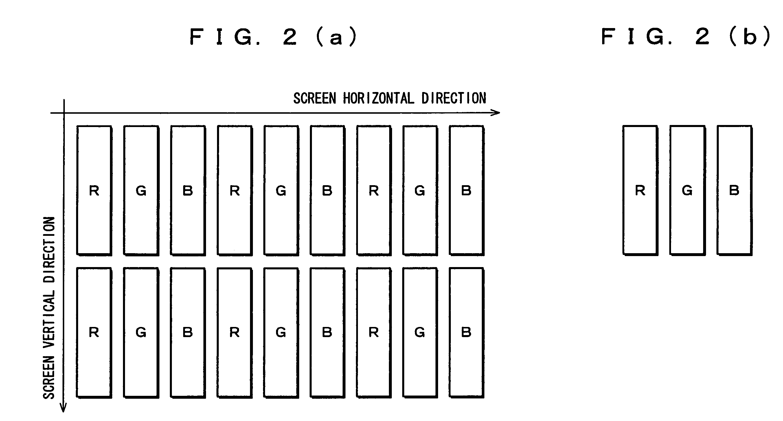
[0120]The following description will explain an embodiment regarding the motion picture pseudo contour correcting method of the present invention, with reference to FIGS. 2(a), 2(b), through 24.

[0121]The present embodiment will be explained by taking as an example a method for correcting a motion picture pseudo contour in the case where a driving sequence based on the time division gray scale display method in combination with the pixel division method is applied to a ferroelectric liquid crystal display, a plasma display panel (hereinafter referred to as PDP), etc. as a display device with a large screen, a large capacity, and a multiple-gray-level display.

[0122]Incidentally, the motion picture pseudo contour correcting method of the present invention is arranged so as to achieve higher precision in motion picture pseudo contour correction than conventionally, in the case where at least the time division gray scale display method is adopted to a method or a device carrying out half...

second embodiment

[0206]The following description will explain another embodiment of a motion picture pseudo contour correcting method in accordance with the present invention, while referring to FIGS. 25 through 34.

[0207]2.1 Driving Sequence

[0208]The following description will explain an embodiment of a driving sequence in which a time ratio for division of a display period of one field is changed to 8:4:1:8 while one pixel remains divided into two sub-pixels at an area ratio of 2:1.

[0209]In this case as well, second redundancy signal patterns 1 through 3 having three redundancies, respectively, can be produced as shown in FIGS. 25 through 27, as the signal patterns of the 64-level gray scale display.

[0210]Comparing the present case with the time division ratio of 8:4:1:8 with the case previously described with the time division ratio of 1:8:4:8, these two cases differ in the gray level turbulence, because of difference between their light emission centers.

[0211]More specifically, in the case of 1:8...

third embodiment

[0235]The following description will explain an embodiment of an image display device employing the motion picture pseudo contour in accordance with the present invention, while referring to FIGS. 35 through 37.

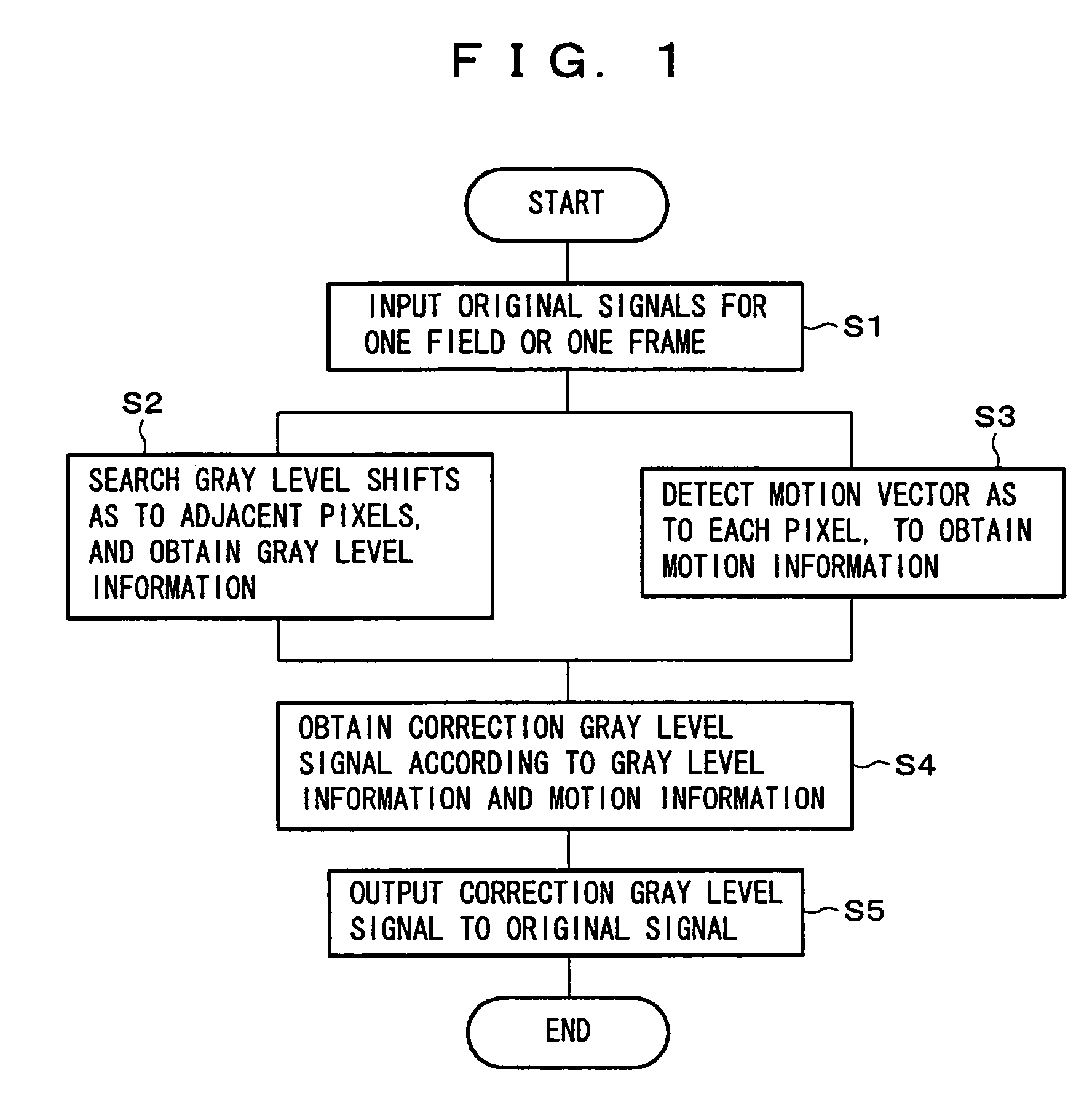
[0236]An image display device in accordance with the present embodiment is provided with a pseudo contour correcting formula classifier 10, a motion detecting section 20, and a correction gray level inserting unit 30, as principal components involved in correction of a motion picture pseudo contour, as shown in FIG. 35.

[0237]First of all, outlines of arrangements and functions of the foregoing components are described below, while detailed operations of the same will be described later.

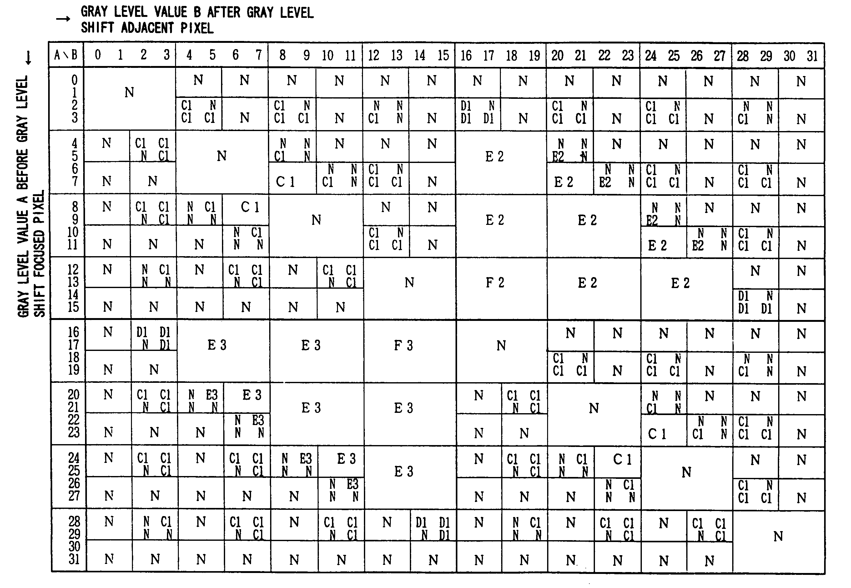
[0238]The foregoing pseudo contour correcting formula classifier 10 holds table data that provide correspondences of gray level shifts to correction patterns as shown in FIGS. 20 through 23 and 30 through 33. In the table data, however, the correction patterns are classified as correcting formu...


PUM


Abstract

A gray level shift is detected as to adjacent pixels in the same field as that of an original signal inputted, so that gray level information is obtained. Concurrently with this step, a motion speed of the picture is detected as to each pixel of the original signal, so that motion information is obtained. A correction gray level signal according to the foregoing gray level information and motion information is obtained, and the correction gray level signal is outputted to the original signal. It therefore results in that a motion picture pseudo contour is detected as to two factors of space and time, and hence, not only the magnitude of gray level turbulence but also a range of pixels affected by the gray level turbulence can be accurately detected.

Description

FIELD OF THE INVENTION[0001]The present invention relates to an image display device capable of half-tone display by the time division method in which one field period or one frame period in image display is divided into a plurality of sub-fields, such as a plasma display panel or a ferroelectric liquid crystal display, and particularly relates to correction of a motion picture pseudo contour that is a problem peculiar to this type of image display devices.BACKGROUND OF THE INVENTION[0002]Recently, a plasma display panel (hereinafter referred to with its abbreviation, “PDP”) and a ferroelectric liquid crystal display have drawn attention as a display device with which display in a large screen, great display capacity, and multiple-gray-level display can be realized.[0003]For example, a PDP generally adopts the time division gray-scale display method as follows: in advance, one field (or called as one frame in some cases: either of the same defines 60 Hz cycle) period is divided into...

Claims


Application Information

Patent Timeline
Patent Type & Authority Patents(United States)
IPC IPC(8): G09G5/10H04N5/208G09G3/20H04N5/14H04N5/66
CPCG09G3/2029H04N5/142G09G3/2074G09G3/2077H04N5/145G09G2320/0266G09G2320/106G09G2320/0261
Inventor OKAMOTO, SHIGETSUGUKYOMOTO, TADAO
Owner SHARP KK
Learn More