Eureka AIR delivers breakthrough ideas for toughest innovation challenges, trusted by R&D personnel around the world.

Self-adjusting interferometric outcoupler and method

an interferometer and outcoupler technology, applied in the optical field, can solve the problems of high oscillator power, low coupling efficiency of the master oscillator input path, and inefficient injection of the oscillator beam into the amplifier beamlin

Inactive Publication Date: 2006-01-31
RAYTHEON CO
View PDF11 Cites 8 Cited by
  • Summary
  • Abstract
  • Description
  • Claims
  • Application Information

AI Technical Summary

Problems solved by technology

However, it was not efficient in the injection of the oscillator beam into the amplifier beamline.
The coupling efficiency of the master oscillator input path, however, may be very low for these devices, necessitating a relatively high power master oscillator.
High oscillator power is problematic for two reasons: (1) reduced overall efficiency of the MOPA and (2) difficulty in obtaining high oscillator beam quality.
The HEL application, however, calls for hundreds of kilowatts to megawatts of average power, which is beyond the current state-of-the-art in Faraday devices.
A problem with these prior art interferometric outcoupler approaches is that they must be used with a PCM that which has a fixed and predetermined frequency shift, typically an SBS PCM.
The SBS PCM has several disadvantages: it does not work well with continuous waveforms, and it requires high peak power but cannot handle high average power.
Furthermore, the prior art interferometric outcoupler approaches are sensitive to length changes in the interferometer optical paths resulting from thermal expansion and warping of the structure, plastic deformation and creep, shock and vibration induced structural compliance, or refractive index changes of the optics and intervening atmosphere, as well as any changes in the frequency of operation of the oscillator or phase conjugate mirror.

Method used


Image

  • Self-adjusting interferometric outcoupler and method
  • Self-adjusting interferometric outcoupler and method
  • Self-adjusting interferometric outcoupler and method

Examples


Embodiment Construction

[0028]Illustrative embodiments and exemplary applications will now be described with reference to the accompanying drawings to disclose the advantageous teachings of the present invention.

[0029]While the present invention is described herein with reference to illustrative embodiments for particular applications, it should be understood that the invention is not limited thereto. Those having ordinary skill in the art and access to the teachings provided herein will recognize additional modifications, applications, and embodiments within the scope thereof and additional fields in which the present invention would be of significant utility.

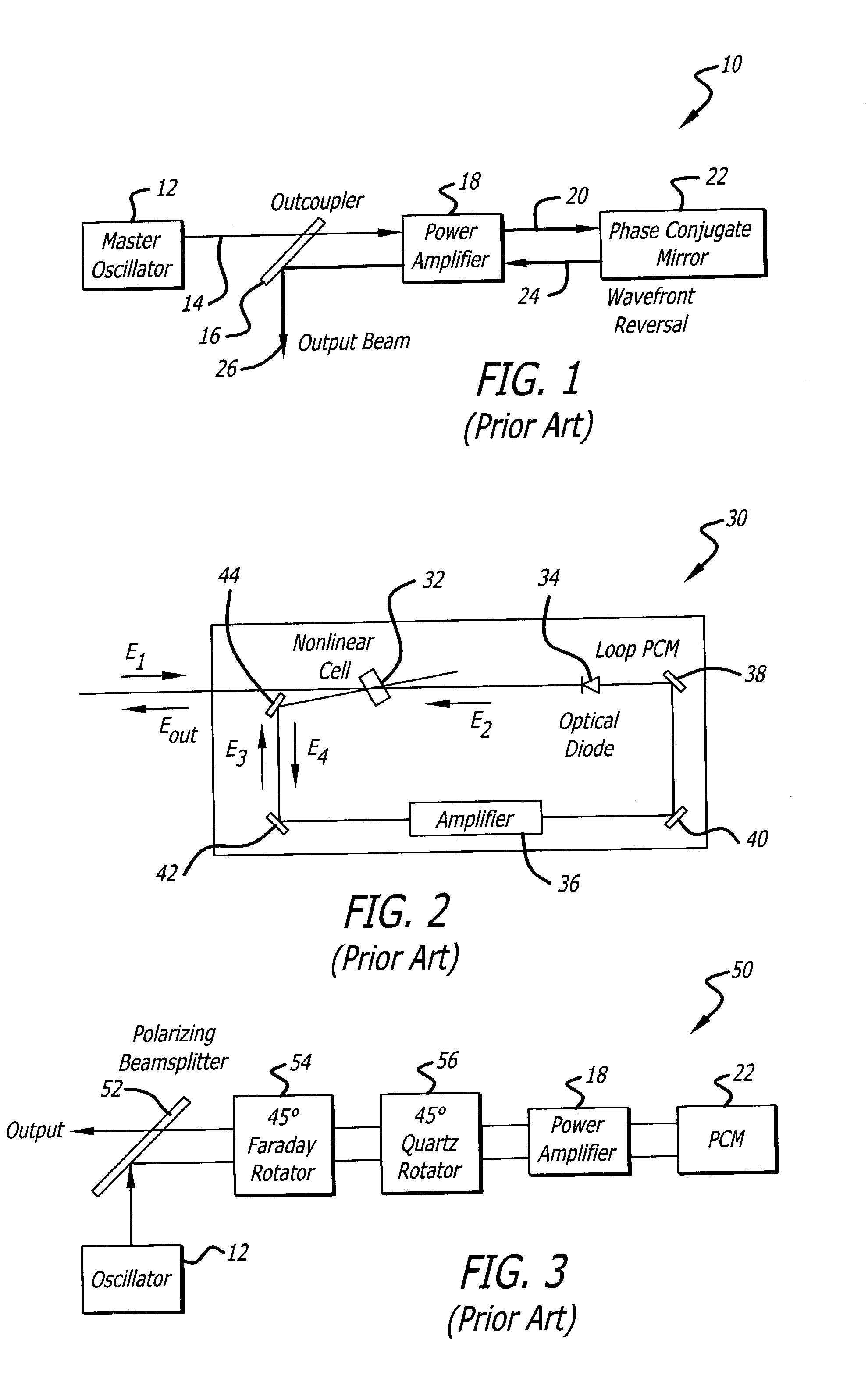
[0030]FIG. 1 is a simplified optical schematic of a basic phase conjugate (PC) master oscillator / power amplifier (MOPA) configuration 10 of conventional design and construction. A small master oscillator 12 delivers a low-power single-mode reference beam 14 through an optical input / output coupler element (hereinafter outcoupler) 16 to the output end ...


PUM


Abstract

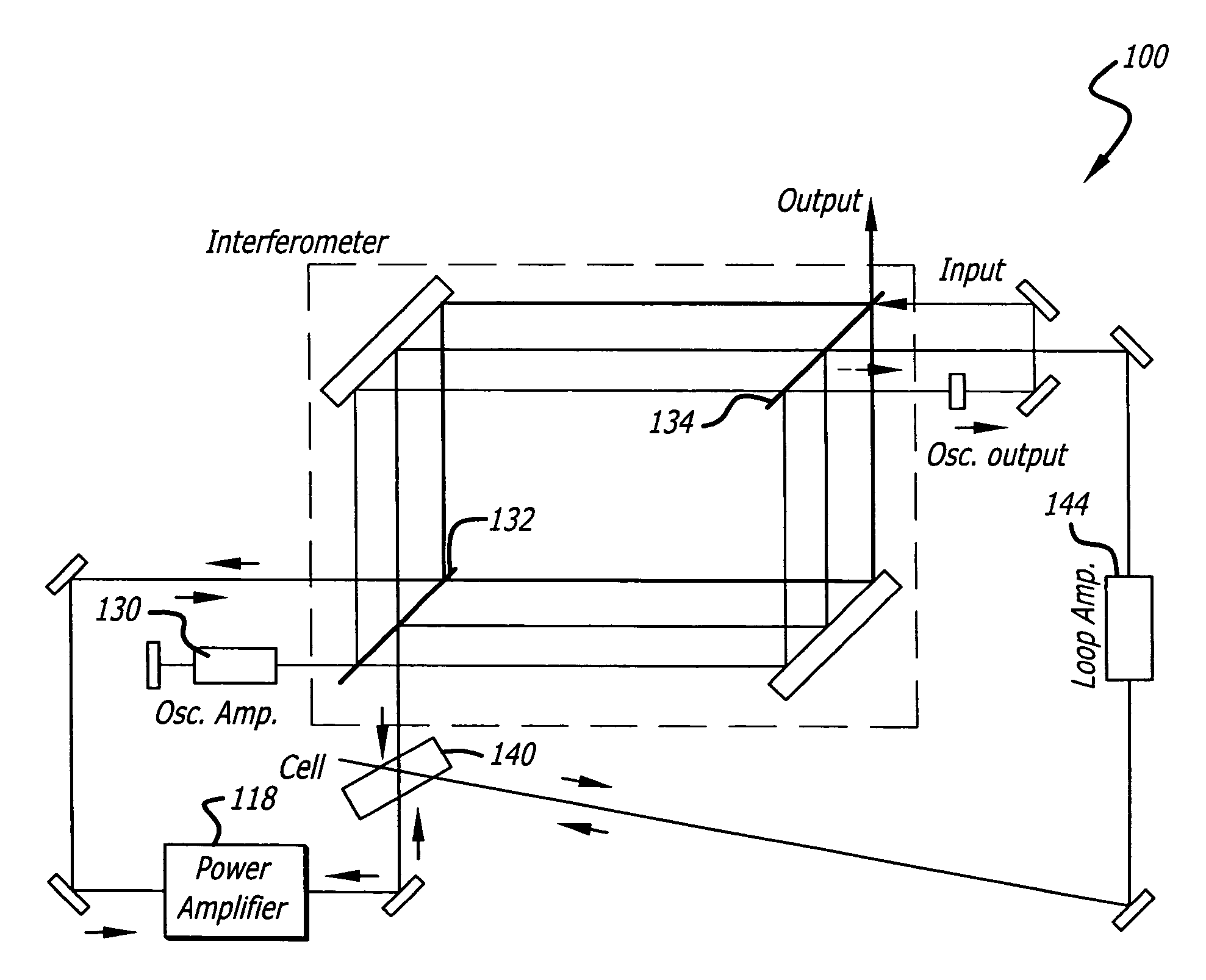
A self-adjusting interferometric outcoupler. In the most general sense, the invention is an optical system (100) comprising a first mechanism (112) for generating a first beam, a second mechanism (122) for receiving the first beam and returning a second beam, and an interferometer (116) positioned to couple the first beam to the second mechanism (122) and to receive and output the second beam, wherein the interferometer (116) is also shared by the first mechanism (112) and / or the second mechanism (122) to control the frequency of the first beam and / or the second beam, respectively. In the illustrative embodiment, the first mechanism (112) is a master oscillator, the second mechanism (122) is a phase conjugate mirror, and the system (100) further includes a power amplifier (118) positioned to amplify the first beam during a first pass and to amplify the second beam during a second pass.

Description

BACKGROUND OF THE INVENTION[0001]1. Field of the Invention[0002]The present invention relates to optics. More specifically, the present invention relates to outcouplers for master oscillator power amplifier (MOPA) systems.[0003]2. Description of the Related Art[0004]The High Energy Laser (HEL), because of its rapid time of flight, pointing agility, precision, lack of collateral damage effects, and lack of traceable residue, is an effective weapon against a broad range of military targets. The diode-pumped solid-state laser, because of its high electrical efficiency, relatively low weight, compact packaging, lack of consumables (except sunlight or fuel), and lack of toxic and corrosive effluents is compatible with many military platforms, including fixed installations, ground vehicles, surface ships, submarines, rotocraft, tactical and strategic aircraft, and spacecraft.[0005]One of the most attractive approaches for a continuous operation weapon-class, high brightness solid-state la...

Claims


Application Information

Patent Timeline
Patent Type & Authority Patents(United States)
IPC IPC(8): H04B10/12H01S3/00H01S3/10H01S3/106H01S3/23
CPCH01S3/2333H01S3/10076
Inventor BETIN, ALEXANDER A.BYREN, ROBERT W.FRANZ, DANA P.
Owner RAYTHEON CO
Why Eureka
Eureka Blog
Learn More