
System and method for router multicast control

a router and multicast control technology, applied in the field of optical communication networks, can solve the problems of delay or block, inability to store or replicate data, and memory on the input card can be exhausted,

Inactive Publication Date: 2006-01-31
AVAGO TECH INT SALES PTE LTD
View PDF18 Cites 18 Cited by
  • Summary
  • Abstract
  • Description
  • Claims
  • Application Information

AI Technical Summary

Benefits of technology

[0007]Transfer of the multicast packet to multiple destinations can occur sequentially over multiple switching cycles or can occur simultaneously. In some embodiments the switching fabric is subdivided into multiple subplanes, such that multiple parallel switching paths exist through the switching fabric. This enables simultaneous parallel multicasting to multiple destinations during a single switching cycle. Some embodiments of the present invention include multiple dedicated multicast cards. This configuration allows rapid expansion of the multicast tree to a large number of destinations.

Problems solved by technology

A router switch fabric that has no inherent storage or replication capability, for example an optical switch fabric, cannot fundamentally multicast packets.
Although this will function and perform the multicast operation, a drawback is that the packet sits in memory on the input card, and if sufficient numbers of multicast packets arrive, the memory on the input card can be exhausted, or the memory can back up subsequent nonmulticast packets and delay or block them from getting through the switching fabric.

Method used


Image

  • System and method for router multicast control
  • System and method for router multicast control
  • System and method for router multicast control

Examples


Embodiment Construction

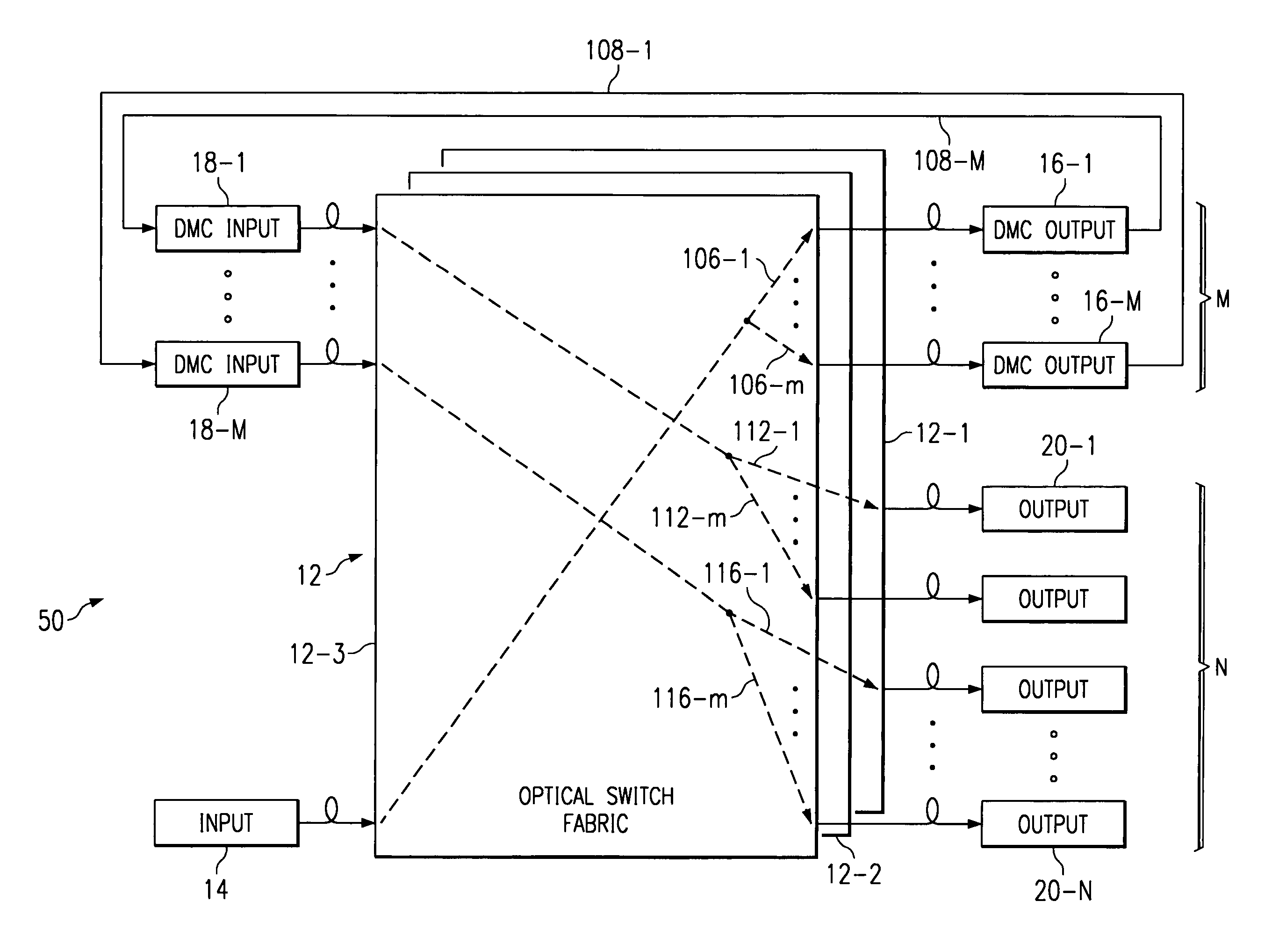
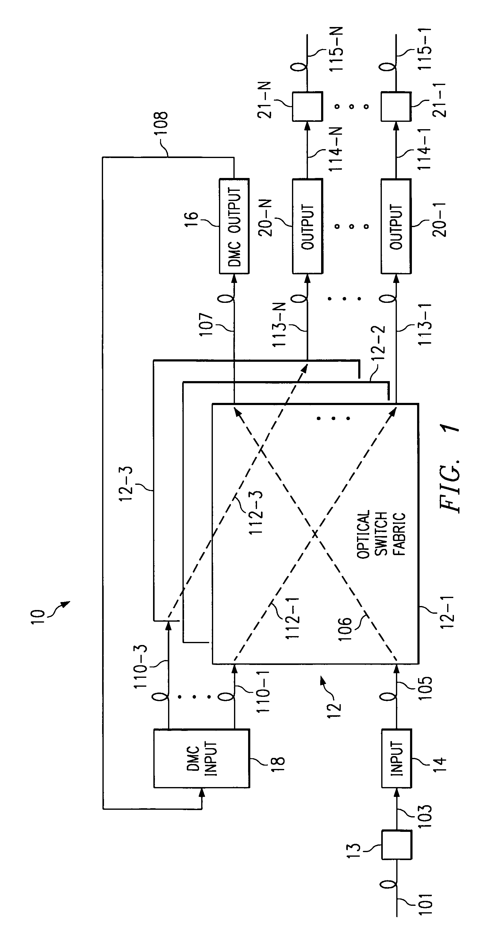
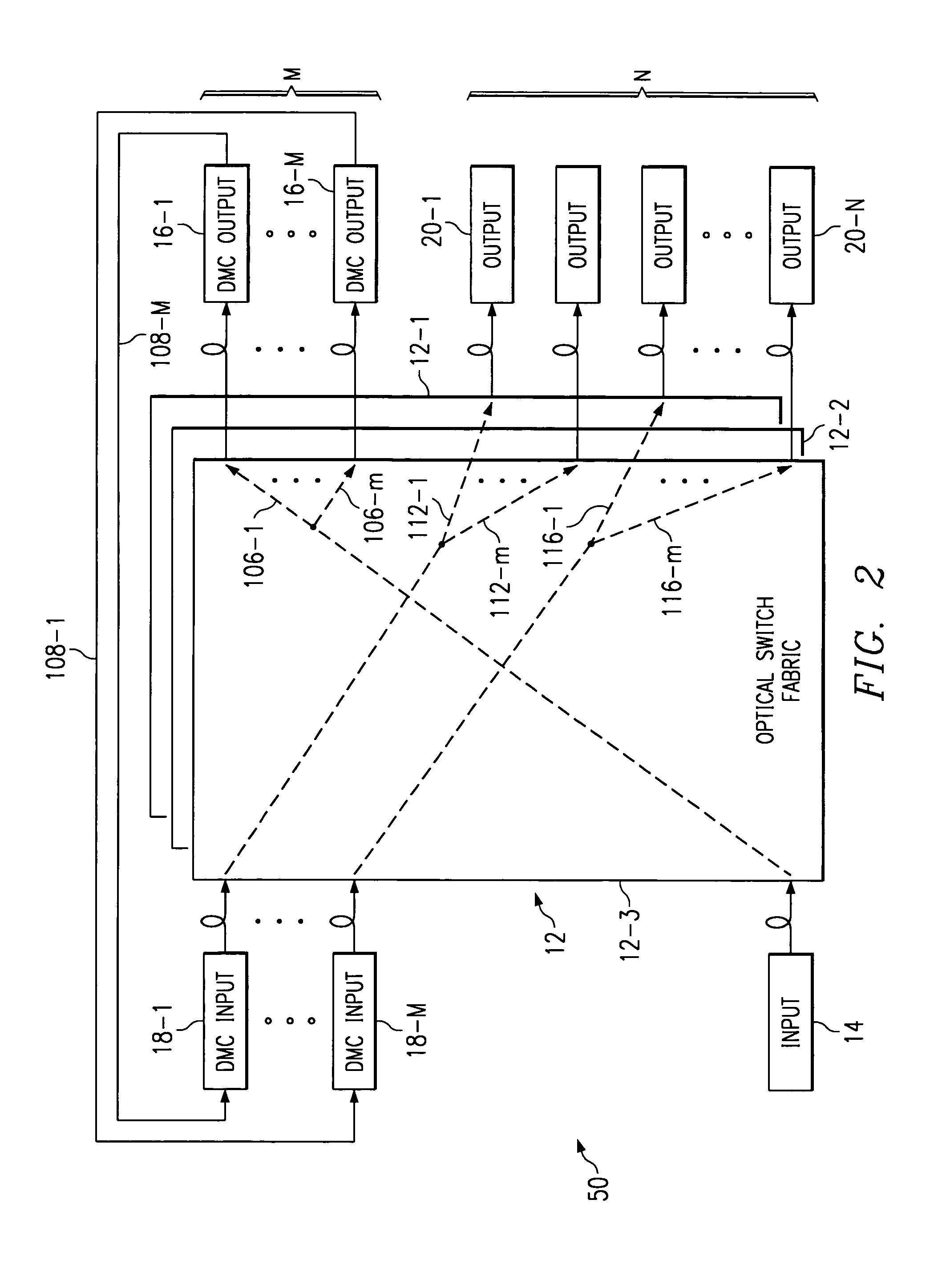
[0013]FIG. 1 is a block diagram illustrating multicast data packet flow through a router system 10 having an optical switching fabric 12, in accordance with an embodiment of the present invention. Optical switching fabric 12 can be partitioned into multiple switching subplanes, for example subplanes 12-1 through 12-3, each having multiple inputs and outputs, which are interconnected dynamically in input / output pair configurations through the optical switch, for example through switching paths 106 and 112-1 through 112-3. The inputs of optical switching fabric 12 are interconnected with multiple input line cards, represented for clarity in FIG. 1 by input line card 14 interconnected through optical link 105 with optical switching fabric 12. Each input line card 14 is in turn interconnected through an electrical link 103 with an input facility interface card 13. Input facility interface card 13 is connected through optical input data path 101 with other network systems, for example pe...


PUM


Abstract

A multicast packet is transferred through a switching fabric from an input line card to a dedicated multicast card, which is substantially the same as an input and output line card, but without external facility interfaces. A dedicated output multicast card converts the multicast packet from an optical to an electrical packet and passes it to a dedicated input multicast card, where the packet is replicated electrically, converted back to an optical packet, and then transferred through the switching fabric to multiple destinations. In some embodiments, input and output dedicated multicast cards are actually a single card. Transfer of the multicast packet to multiple destinations occurs sequentially or simultaneously during a single switching cycle, if multiple parallel switching paths exist through the switching fabric. Some embodiments include multiple dedicated multicast cards, allowing rapid simultaneous expansion of the multicast tree.

Description

RELATED APPLICATIONS[0001]This application is related to co-pending and commonly assigned U.S. application Ser. No. 09 / 703,057, entitled “system And Method For IP Router With an Optical Core,” to co-pending and commonly assigned U.S. application Ser. No. 09 / 703,056, entitled “System and Method for Router Central Arbitration,” to co-pending and commonly assigned U.S. application Ser. No. 09 / 703,038, entitled “System and Method for Router Data Aggregation and Delivery,” to co-pending and commonly assigned U.S. application Ser. No. 09 / 702,958, entitled “Timing and Synchronization for an IP Router Using an Optical Switch,” now issued as U.S. Pat. No. 6,711,357 to co-pending and commonly assigned U.S. application Ser. No. 09 / 703,027, entitled “Router Network Protection Using Multiple Facility Interfaces,” to co-pending and commonly assigned U.S. application Ser. No. 09 / 703,043, entitled “Router Line Card Protection Using One-for-N Redundancy” now issued as U.S. Pat. No. 6,879,559, and to...

Claims


Application Information

Patent Timeline
Patent Type & Authority Patents(United States)
IPC IPC(8): H04J1/00H04L12/56H04Q11/00
CPCH04L49/201H04Q11/0005H04L49/203H04L49/1523H04Q2011/0047H04Q2011/0039
Inventor MCDERMOTT, III, THOMAS C.KLEINER, JIM
Owner AVAGO TECH INT SALES PTE LTD
Features
  • Generate Ideas
  • Intellectual Property
  • Life Sciences
  • Materials
  • Tech Scout
  • Unparalleled Data Quality
  • Higher Quality Content
  • 60% Fewer Hallucinations
Learn More