Backup power supply device for a storage device

a storage device and power supply technology, applied in the field of backup techniques for storage devices, can solve the problems of limited backup period, risk of losing a part of the inability to completely write the data retained by the cache memory to the hdd, so as to achieve high reliability without increasing the size or cost of the storage devi

Inactive Publication Date: 2006-01-31
HITACHI LTD
View PDF11 Cites 24 Cited by
  • Summary
  • Abstract
  • Description
  • Claims
  • Application Information

AI Technical Summary

Benefits of technology

[0009]An object of the present invention is therefore to make it possible, in a storage device having a disk driving device and a cache memory, to secure data retained by the cache memory with high reliability without increasing the size or cost of the storage device.

Problems solved by technology

However, in this method, there may occur a case that data retained by the cache memory cannot be written to the HDD completely, because the processing of transferring the data inside the storage device and a circuit configuration relating to the writing of the data to the HDD are complex and the execution of the above kinds of processing requires a large number of devices.
That is, there is a risk of losing part of data retained by the cache memory.
In the second method, when a power failure has occurred, low power is supplied from a backup power source to only the cache memory for as relatively long a time as several days to back up only the cache memory.
However, the period during which data retained by the cache memory are secured, that is, the backup period, is limited because a battery module as the backup power source can supply power only in a period determined by its capacity.
As described above, it is difficult for either of the two methods to completely secure data retained by the cache memory.
On the other hand, employing both methods increases the size of the battery module that is incorporated in the storage device.
As a result, not only the size of the storage device itself but also the device cost is increased.

Method used


Image

  • Backup power supply device for a storage device
  • Backup power supply device for a storage device
  • Backup power supply device for a storage device

Examples


Embodiment Construction

[0024]An embodiment of the present invention will be hereinafter described in detail with reference to the drawings.

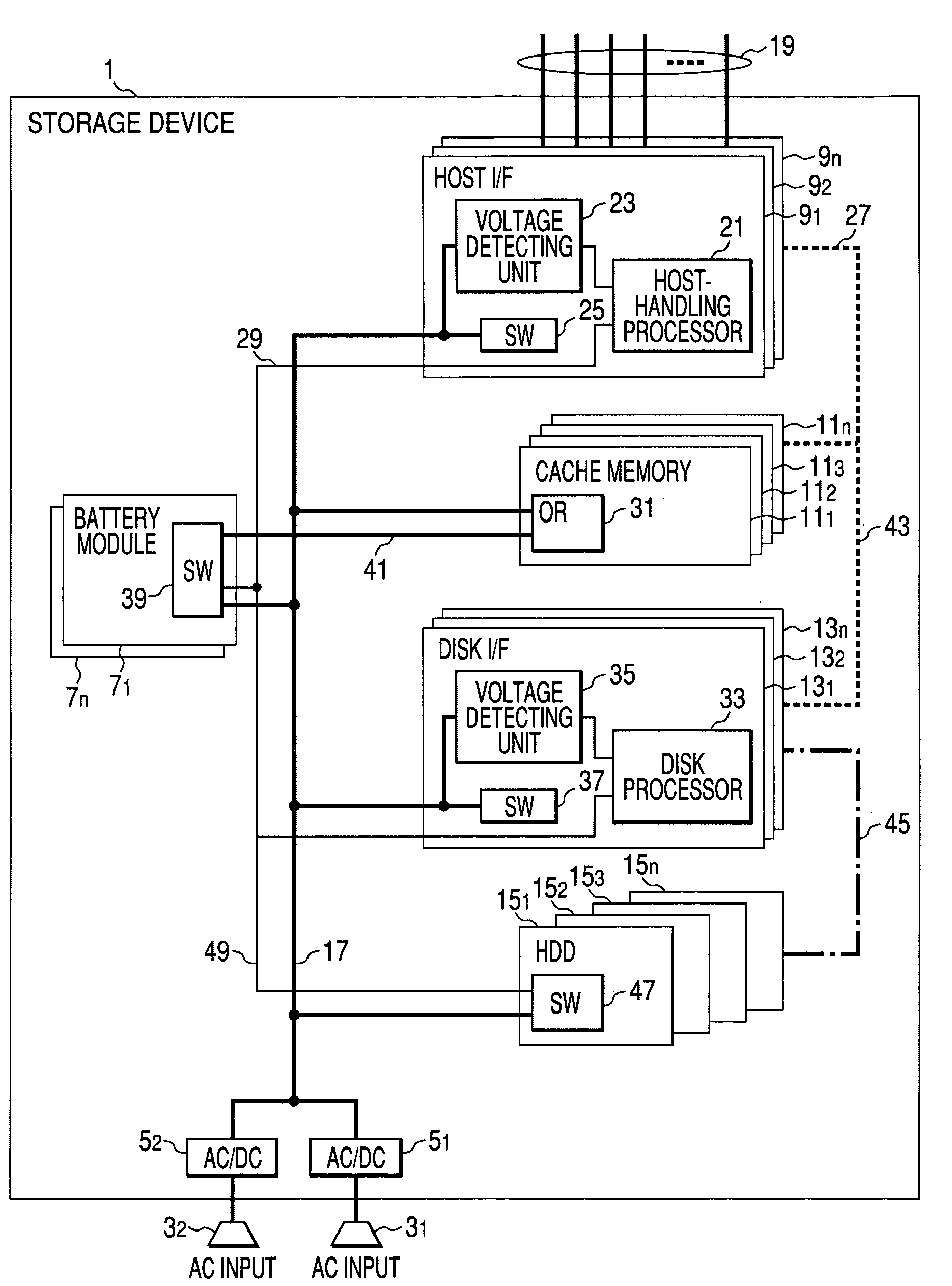
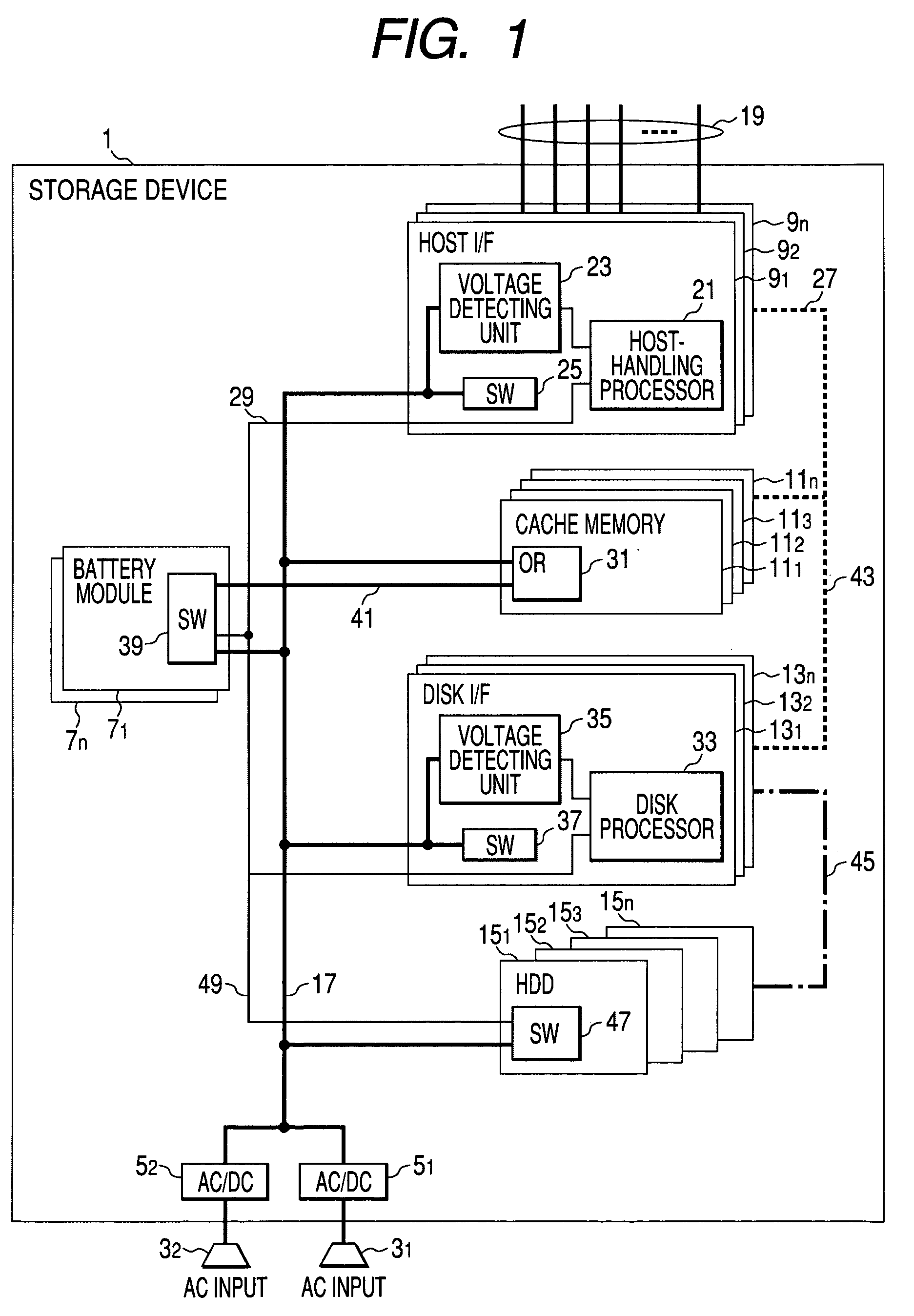
[0025]FIG. 1 is a block diagram showing the entire configuration of a storage device according to the embodiment of the invention.

[0026]As shown in FIG. 1, the storage device 1 is equipped with a plurality of (in FIG. 1, two) AC inputs; hereinafter referred to as “commercial power input units”) 31 and 32, a plurality of (in FIG. 1, two) AC / DC converters 51 and 52, a plurality of battery modules 71–7n, a plurality of host interfaces (hereinafter abbreviated as “host I / F's”) 91–9n, and a plurality of cache memories 111–11n. The storage device 1 is also equipped with a plurality of disk interfaces (hereinafter abbreviated as “disk I / F's”) 131–13n and a plurality of hard disk drives (hereinafter abbreviated as “HDDs”) 151–15n.

[0027]In this embodiment, as shown in FIG. 1, the two commercial power input units 31 and 32 are provided. Therefore, the two AC / DC converters 51 and...


PUM

PropertyMeasurementUnit
DC voltageaaaaaaaaaa

Abstract

An object of the invention is to make it possible to secure data retained by a cache memory with high reliability without increasing the size or cost of a storage device. When a host-handling processor and a disk processor have recognized occurrence of a power failure, operation of a storage device is continued for about one minute on DC power that is supplied from a battery module. After a lapse of one minute from the occurrence of the power failure, the host-handling processor interrupts the connection between the storage device and a host. Then, the host-handling processor turns off a SW of a host I / F and the disk processor writes, to an HDD, data that have been written to a cache memory. After completion of this processing, the disk processor turns off a SW of the disk I / F and a SW of the HDD. Then, the disk processor causes the battery module to supply DC power only to the cache memory.

Description

CROSS-REFERENCE TO RELATED APPLICATION[0001]This application relates to and claims priority from Japanese Patent Application No. 2003-400170, filed on Nov. 28, 2003, the entire disclosure of which is incorporated herein by reference.BACKGROUND OF THE INVENTION[0002]The present invention relates to a backup technique for a storage device that is equipped with a disk driving device for storing data received from an information processing apparatus and a cache memory for temporarily retaining data to be stored in the disk driving device.[0003]A disk array device in which an uninterruptible power source having a minimum necessary rated output power is used as a means for reliably backing up a cache memory having a large storage capacity is known. In this disk array device, a write cache save area that is separate from a user data area is formed in each of a plurality of HDDs (hard disk drives) that constitute an arbitrary array among a plurality of arrays that are managed by a disk arra...

Claims


Application Information

Patent Timeline
Patent Type & Authority Patents(United States)
IPC IPC(8): G06F11/00G06F1/26G06F12/16G06F1/30G06F3/06G11B20/10
CPCG06F1/30
Inventor FUKUMORI, MITSUO
Owner HITACHI LTD
Why Eureka
Try Eureka