Pipe preparation device

a pipe preparation and pipe technology, applied in the direction of manufacturing tools, circular curve drawing instruments, portable lathes, etc., can solve the problem of difficult to be sure that the joint is formed

Inactive Publication Date: 2006-02-07
VICTAULIC
View PDF31 Cites 17 Cited by
  • Summary
  • Abstract
  • Description
  • Claims
  • Application Information

AI Technical Summary

Benefits of technology

[0008]The device may also include additional receptacles positioned within the body. The additional receptacles are sized to receive the end of one of the pipes and also have one or more tools mounted and positioned so as to engage the pipe upon its insertion within the additional receptacles. The tools associated with the receptacles may also be marking tools and cutting blades substantially as described above for the first receptacle. Preferably, when two receptacles are present, the first and second receptacles are substantially coaxially aligned with one another and are sized to receive pipes of different diameters. Furthermore, an elongated shaft may be mounted on the body. Preferably, such a shaft has a polygonal cross-section (preferably hexagonal). When mounted, the shaft is oriented substantially coaxially with the receptacles and is engageable with a chuck or a compatible extension shaft such as used with a rachet wrench, power drill or other powered device. The presence of the shaft allows the body to be rotated relatively to the pipe upon rotation of the shaft by the drill or other powered device. Preferably, the shaft extends substantially coaxially through both the first and the second receptacles allowing the body to be turned from either end.

Problems solved by technology

However, without a visible means to indicate proper engagement of the pipe end with the mechanical coupling it is difficult to be sure that the joint formed will be fluid tight and sufficiently inserted to maximize bending stiffness and strength of the joint.

Method used


Image

  • Pipe preparation device
  • Pipe preparation device
  • Pipe preparation device

Examples


Embodiment Construction

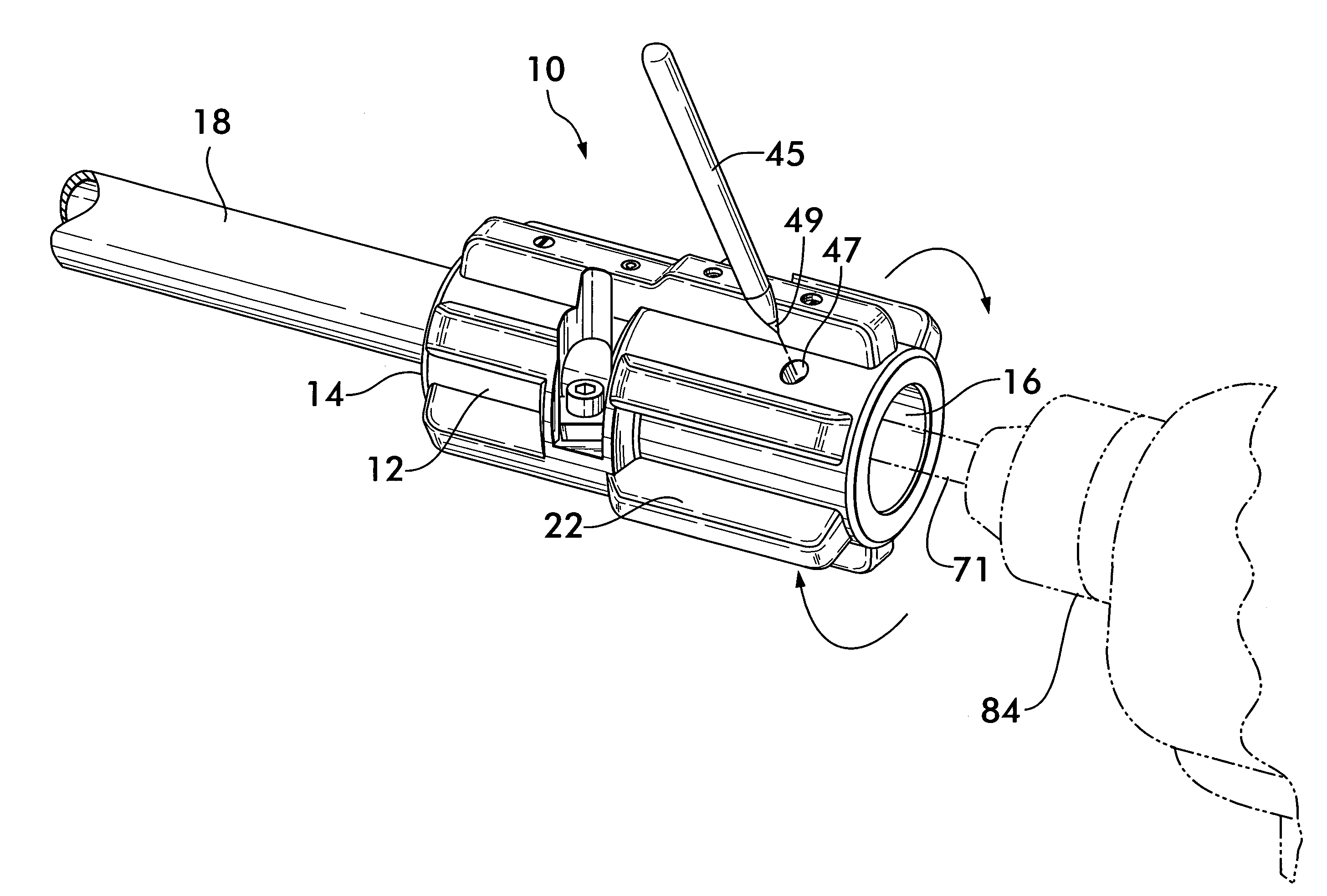
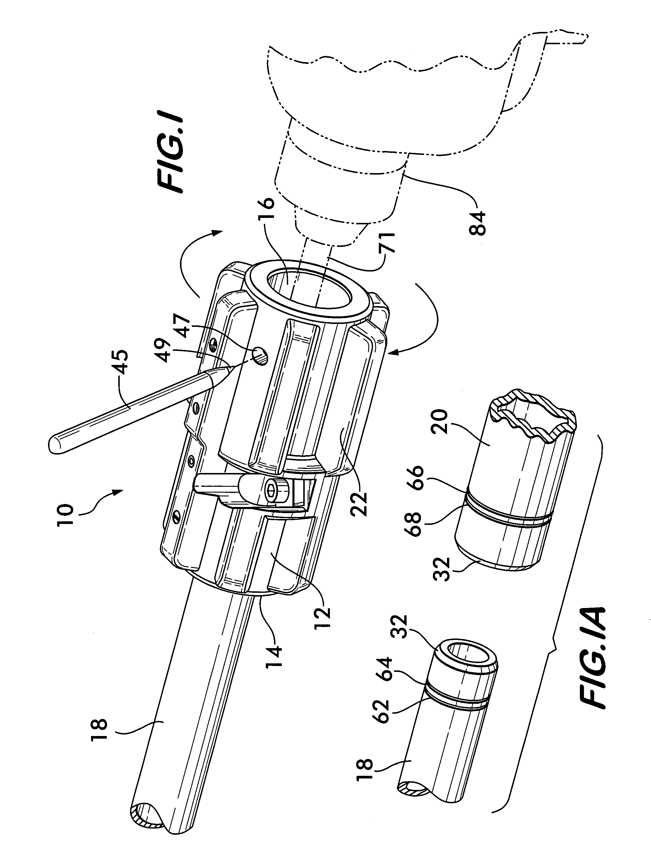
[0020]FIG. 1 shows pipe preparation device 10 according to the invention. Device 10 comprises a body 12 having receptacles 14 and 16 at opposite ends. Preferably, receptacles 14 and 16 are coaxially aligned with one another and are sized to receive pipes 18 and 20, shown in FIG. 1A, the pipes preferably having different diameters from one another. As body 12 must be turned relatively to the pipes 18 and 20 to effect their preparation, it is convenient to provide radially projecting ribs 22 to facilitate manual grasping and rotating of the device 10. Body 12 is preferably formed from durable polymer resin to provide a light-weight, inexpensive and robust item that can withstand rough use.

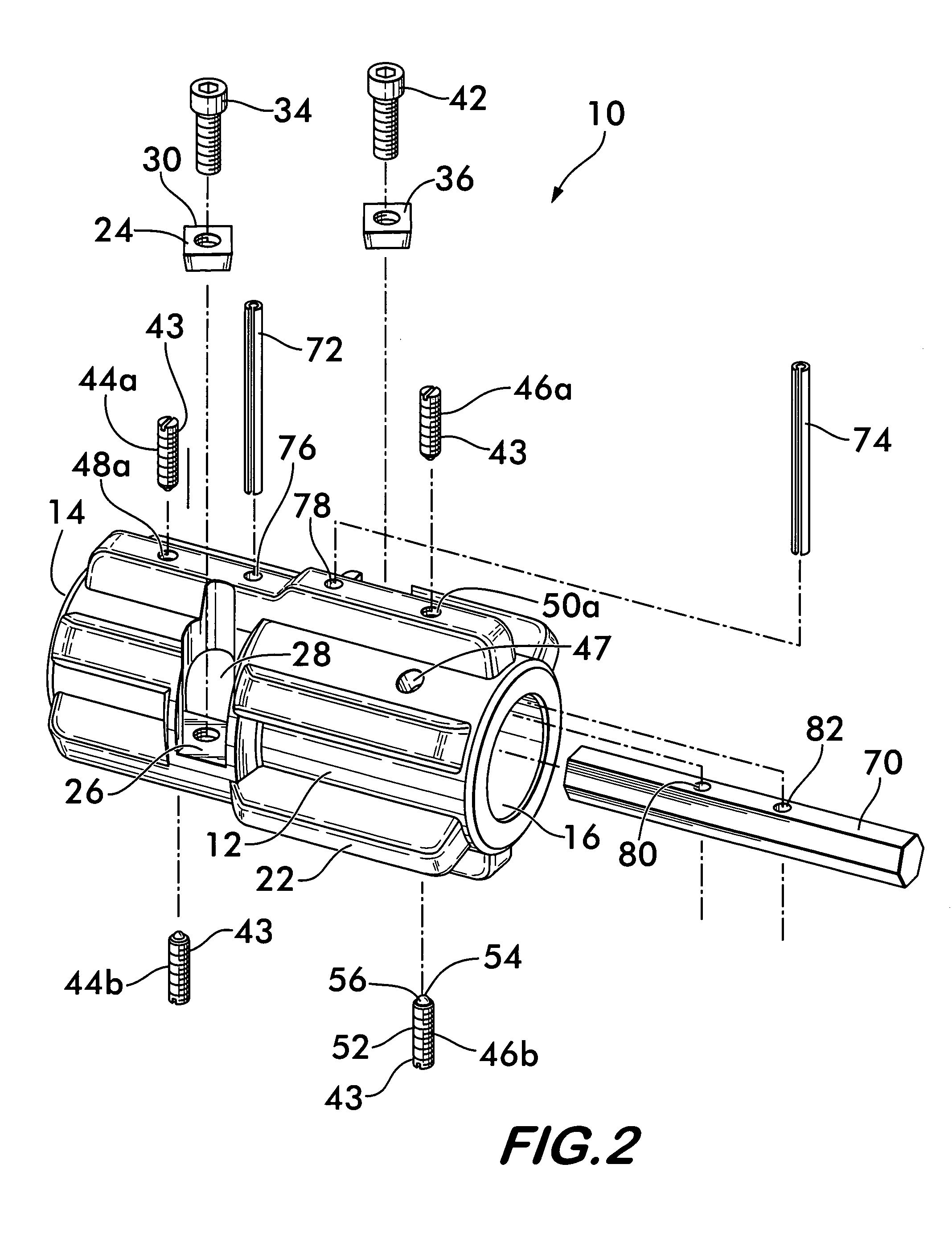
[0021]FIG. 2 provides an exploded view that illustrates the various tools mounted on the body 12 that engage the pipe during its preparation. A cutting blade 24 is mounted on a ledge 26 formed adjacent to an aperture 28 that opens into receptacle 14. As best shown in FIG. 3, the blade 24 has a cuttin...


PUM

PropertyMeasurementUnit
diameteraaaaaaaaaa
hardnessaaaaaaaaaa
diameteraaaaaaaaaa

Abstract

A pipe preparation device is disclosed for chamfering pipe ends and placing witness marks thereon to provide a visible indication that the pipes are properly engaged with a coupling. The device includes a body having co-axially aligned receptacles at opposite ends, the receptacles being sized to receive pipes having different diameters from one another. Cutting blades are mounted on the body and project into each receptacle. The blades have cutting edges that engage the end of a pipe inserted into a receptacle and cut a chamfer when the body is rotated relatively to the pipe. Two scoring tools project into each receptacle. The tools have contact surfaces that engage a pipe inserted into the receptacle. The tools in each receptacle are offset from one another and form two circumferential grooves around the pipe when the body and pipe are rotated relatively to each other. The grooves act as witness marks.

Description

FIELD OF THE INVENTION[0001]This invention concerns tools for preparing pipes for joining to one another, and especially for pipes joined using mechanical pipe couplings.BACKGROUND OF THE INVENTION[0002]Pipes, especially relatively small diameter copper pipes between one half inch and two inches nominal diameter, are used extensively to provide water service for homes, business and industry. Such pipes may be sealingly joined to one another end to end using mechanical couplings to create a piping network for conveying water throughout a building such as a home, office or factory.[0003]Mechanical couplings provide various advantages over traditional solder joints for connecting pipes in that they avoid the use of acid flux, solder and open flame to effect a connection. Assembly of a joint using a mechanical coupling also requires less time than a solder joint and may be performed by a less skilled worker. Assembly of a joint merely requires that a pipe end be inserted into a coupling...

Claims


Application Information

Patent Timeline
Patent Type & Authority Patents(United States)
IPC IPC(8): B23B3/22B25H7/00B43L9/00B43L13/00
CPCB23B5/167B25H7/005B43L13/00B43L9/00Y10T82/22Y10T408/865
Inventor SNYDER, SR., RONALD R.DOLE, DOUGLAS R.
Owner VICTAULIC
Why Eureka
Try Eureka