Locking block for compact semi-automatic pistols

a semi-automatic pistol and locking block technology, applied in the direction of barrel mounting, butts, weapons, etc., can solve the problems of reducing the size of the pistol, limiting the reduction of the pistol size, affecting the loading cycle, etc., and achieve the effect of reducing the relative movement of the block and the fram

Inactive Publication Date: 2006-02-07
SMITH & WESSON
View PDF34 Cites 57 Cited by
  • Summary
  • Abstract
  • Description
  • Claims
  • Application Information

AI Technical Summary

Benefits of technology

[0015]A preferred embodiment of the present invention is a locking block for a compact semi-automatic pistol having a frame, a slide, a barrel and a firing mechanism. The locking block includes a front end having a substantially unshaped opening and a rear end. The block also includes laterally spaced side walls, each side wall having a guide rail which engages a longitudinally extend

Problems solved by technology

If the slide is too light the case is extracted too soon affecting the loading cycle.
In some prior art compact pistols, there is a limit

Method used


Image

  • Locking block for compact semi-automatic pistols
  • Locking block for compact semi-automatic pistols
  • Locking block for compact semi-automatic pistols

Examples


Embodiment Construction

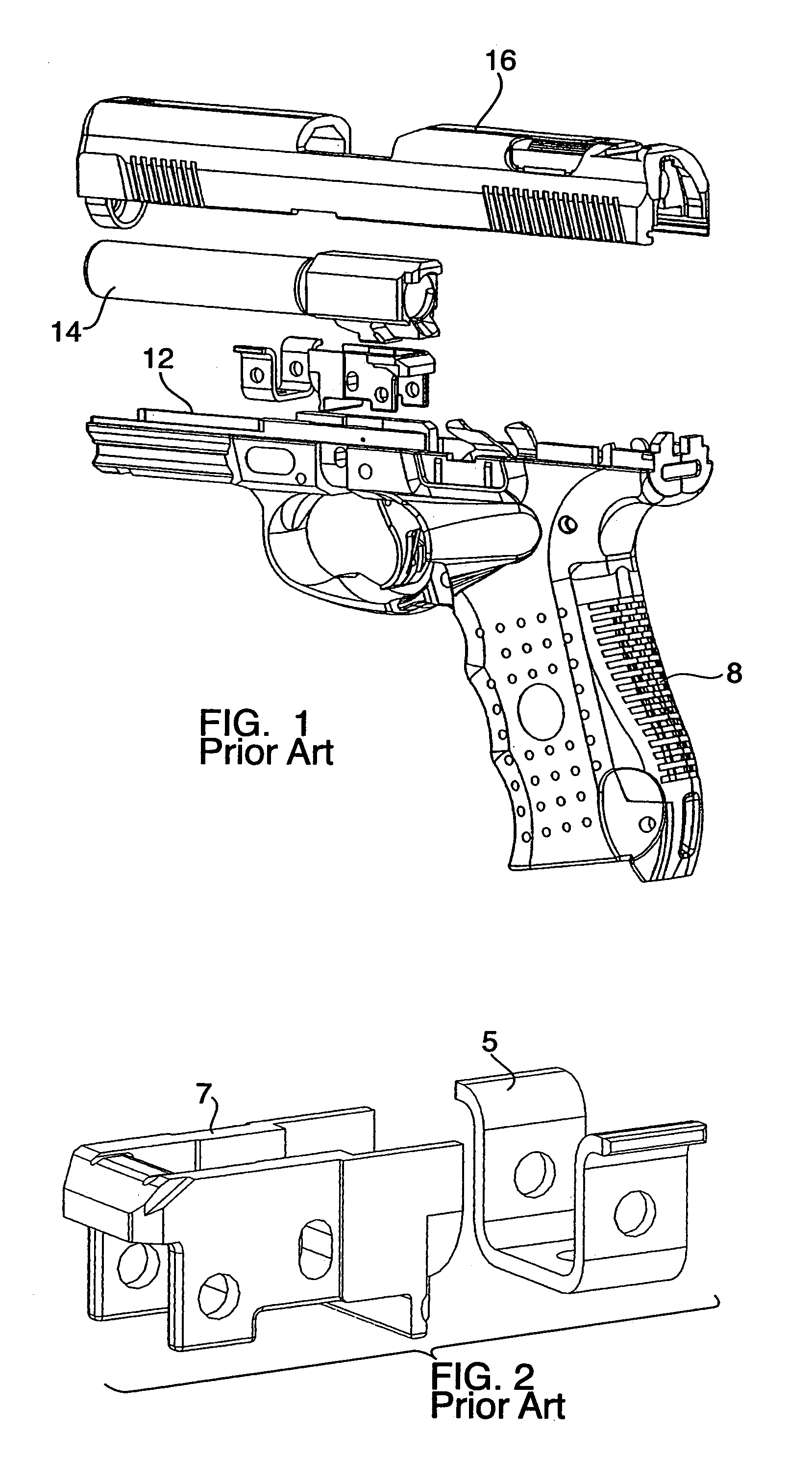
[0025]FIGS. 1 and 2 show prior art locking blocks. FIG. 2 depicts a prior art block in which the guide rails 5 are separate from the block 7. As discussed in detail below, the present invention features a locking block with integral guide rails.

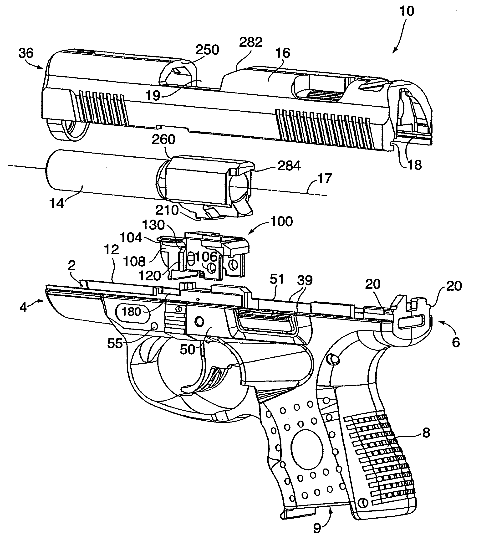
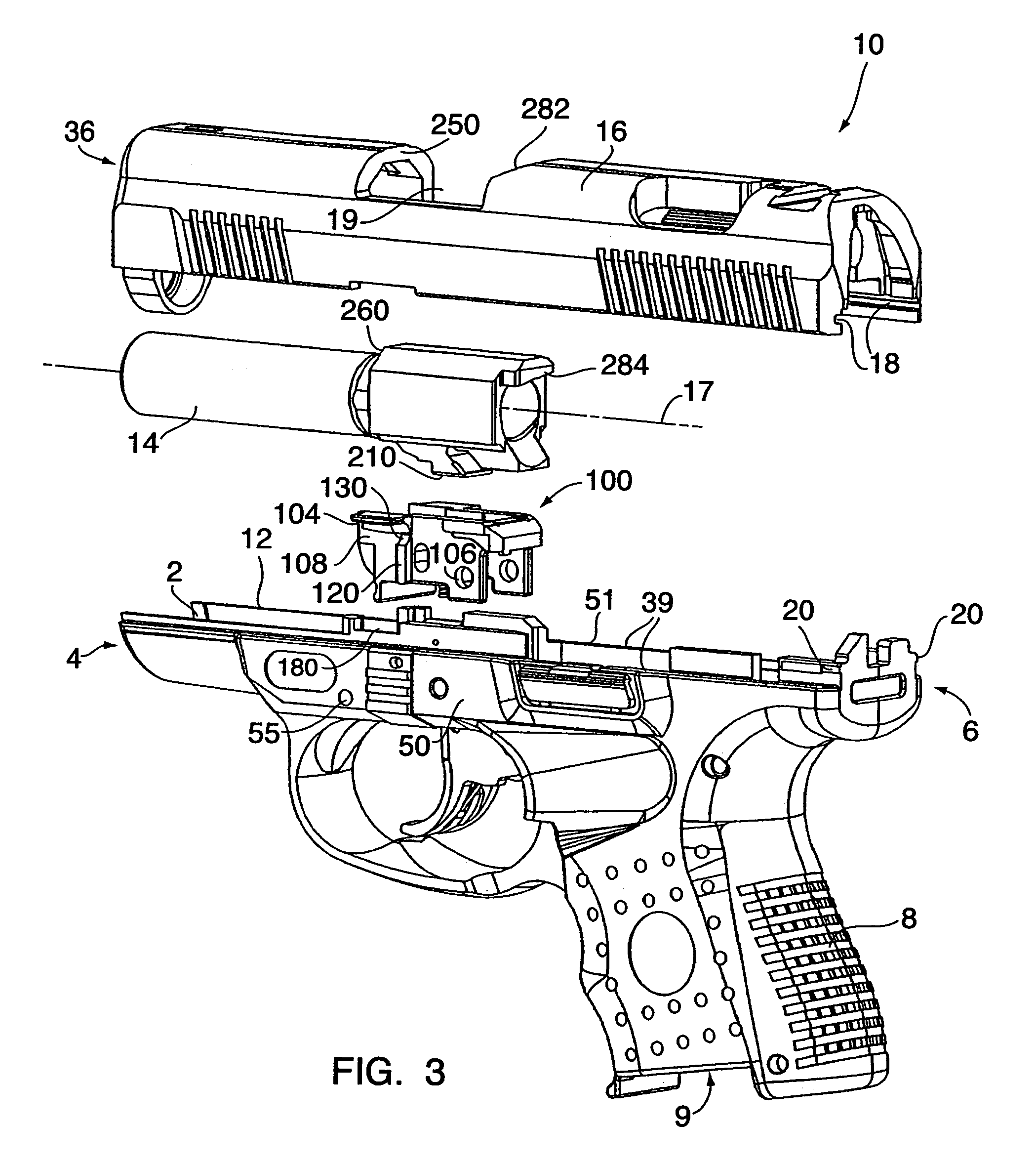
[0026]Referring to FIG. 3, a preferred embodiment of a pistol of the type embodying the present invention is shown. The pistol comprises a polymer frame 12, and a barrel 14 affixed medially of the forward end 4 and after-end 6 of the pistol. A slide 16 is disposed for reciprocal movement relative to the barrel and frame. The barrel has a firing axis 17.

[0027]The frame 12 is preferably a unitary structure fabricated by injection molding a high strength, heat and corrosion resistant polymer, such as Nylon 66™.

[0028]As will be noted in FIG. 3, the frame 12 comprises an upwardly open channel 2 extending over the length of the frame generally from one end 4 to the other end 6 thereof. A handgrip portion 8 of ergonomic configuration is also shown. ...


PUM


Abstract

A locking block mechanism for a compact semiautomatic pistol includes a pair of forward guide rails, which are normally separate from the locking block. Additionally, the locking block includes transverse ribs on the sides of the locking block, which engage mating slots in the polymeric frame of the pistol and secure the block to the frame. The guide rails and transverse ribs are separated by a space or discontinuity on the side wall of the locking block. The guide rails include chamfered front and rear edge surfaces and arcuate, convex bottom surfaces. The above-mentioned features function to create a durable locking block that allows for the construction of a pistol that is more compact than prior art designs.

Description

CROSS REFERENCE TO RELATED APPLICATION[0001]This application claims the benefit of U.S. Provisional Patent Application Ser. No. 60 / 446,407, filed on Feb. 11, 2003, entitled “COMPACT LOCKING BLOCK FOR SEMI-AUTOMATIC PISTOLS” herein incorporated by reference in its entirety.FIELD OF THE INVENTION[0002]The present invention relates generally to a locking block for a semiautomatic pistol and more particularly to a locking block for a compact, polymer frame, high-powered pistol that combines the normally separate guide rails with the locking block.BACKGROUND OF THE INVENTION[0003]Semi-automatic pistols can be divided into a number of different types. These include pistols that use a blowback mechanism and those that utilize a short-recoil Browning-type mechanism.[0004]With blowback pistols, only the slide moves relative to the frame of the gun upon discharge. The barrel of a blowback pistol is fixed to the frame but the slide is not secured to the barrel. Immediately after firing the pis...

Claims


Application Information

Patent Timeline
IPC IPC(8): F41A21/48
CPCF41A5/04F41A3/14
Inventor O'CLAIR, SEANPOULIN, MICHAEL J.FOLEY, KEVIN G.
Owner SMITH & WESSON
Why Eureka
Try Eureka