Large round baler
a baler and large technology, applied in baling, agriculture tools and machines, agriculture, etc., can solve the problems of high positioning force and large height of the carrier
- Summary
- Abstract
- Description
- Claims
- Application Information
AI Technical Summary
Benefits of technology
Problems solved by technology
Method used
Image

Examples
first embodiment
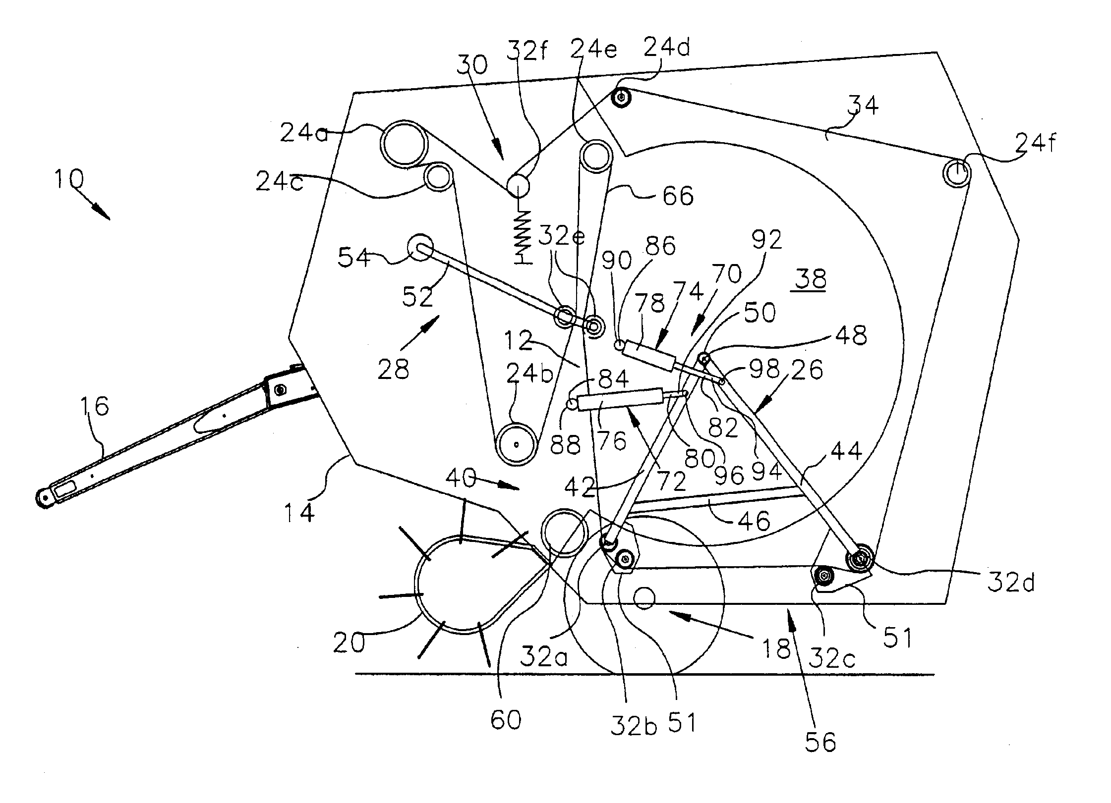
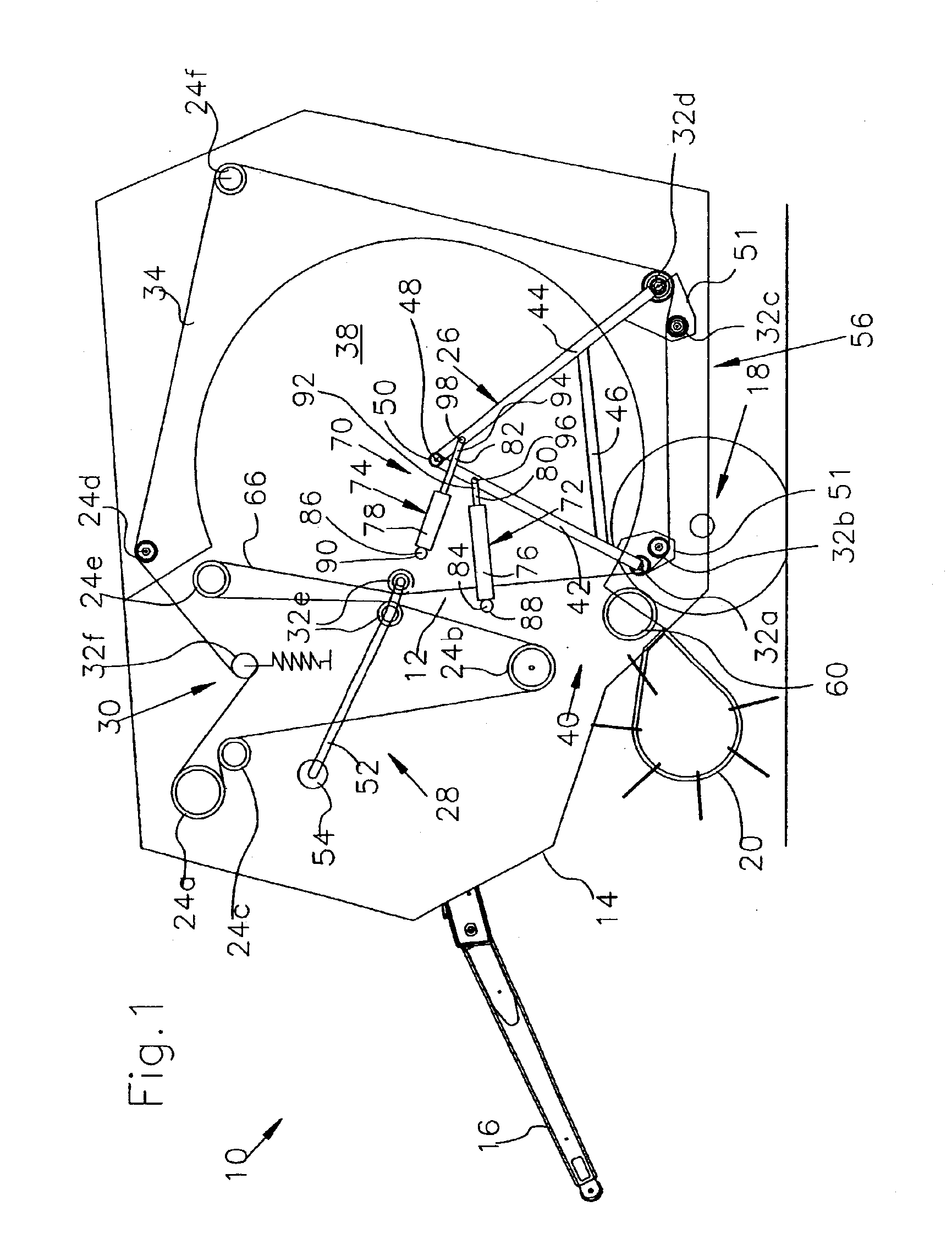
[0045]On the basis of the above description, the large round baler 10 operates as follows.
[0046]As long as no crop is being conducted to the large round baler 10 and the baling chamber 12 is empty, the carrier 26 is located in its lower, forward end position, wherein the first roll 32a that is located on the first leg 42 is near the roll 60, and the rotating rolls 32a-32d are located close to a generally horizontal plane. The tensioning arm 52 is forced to the rear and downward so that it is inclined approximately 30° from the horizontal and disposes the rolls 32e at a central location between the fixed-axis rollers 24b and 24e. Between the rotating rolls 32e, carried by the pivotable tensioning arm 52 and the lower central fixed-axis roll 24e, the bale-forming element(s) 34 forms a loop 66. Finally, a section of the bale-forming element(s) 34, extends from the front side of the movable roll 32e to the front side of the movable roll 32a at a location adjacent a rear side of the fixe...
second embodiment
[0061]FIGS. 7 through 10 show an actuating arrangement 110, with two actuating devices 112 and 114 and a two-piece linkage defined by a first steering arm 116 and a second steering arm 118 for the carrier 26, which is shown here with only one leg 42 for the sake of simplicity. The carrier 26 pivots about the bearing 48 and is provided with an extension 120 generally in the direction of its leg 42 beyond the bearing 48. In an end region 122 of the extension 120, facing away from the leg 42, the extension 120 is fastened to an end region 124 of the first steering arm 116. The end regions 122 and 124 are connected to each other over a bearing 126, free to pivot. The first steering arm 116 is provided with two legs 128 and 130 that extend at an angle of 130° to each other and in whose bend 132 a first end region 134 of the second steering arm 118 is fastened. The end region 134 and the bend 132 are connected to each other over a bearing 136, free to pivot. A second end region 138 of th...
third embodiment
[0067]FIGS. 11 through 14 show an actuating arrangement 180 with an actuating device 182 and a two-piece linkage defined by a first steering arm 184 and a second steering arm 186. The first steering arm 184 has an end region 188 (in FIG. 11 on the left) fastened over a bearing 190 to the side wall 38 or the chassis 14, free to pivot, and a second end region 192 fastened over a bearing 194 to a first end region 196 of the second steering arm 186, free to pivot. A second end region 198 of the steering arm 186 is fastened to a bearing 200, free to pivot. The bearing 200 is part of the carrier 26 or is fastened to it. The arrangement of the steering arms 184 and 186 is selected in such a way that in a lower end position of the carrier 26, the two bearings 194 and 200 are spaced below and respectively forwardly and rearwardly of the pivot axis of the bearing 48. Further, the two steering arms 184 and 186 nearly overlap each other. In this way the spacing of each of one of the bearings 1...
PUM
 Abstract
Description
Claims
Application Information
 - R&D Engineer
- R&D Manager
- IP Professional
- Industry Leading Data Capabilities
- Powerful AI technology
- Patent DNA Extraction
Browse by: Latest US Patents, China's latest patents, Technical Efficacy Thesaurus, Application Domain, Technology Topic.
© 2024 PatSnap. All rights reserved.Legal|Privacy policy|Modern Slavery Act Transparency Statement|Sitemap