Method for magnetic/ferrofluid separation of particle fractions

a magnetic/ferrofluid and particle fraction technology, applied in the direction of magnetic separation, high-grade magnetic separators, chemistry apparatuses and processes, etc., can solve the problems of difficult cleaning of the apparatus, complex structure and fragile available magnetic separation apparatus, and inability to accept or inacceptable ceramic particles, etc., to achieve easy collection, easy cleaning and preparation

Inactive Publication Date: 2006-02-07
GENERAL ELECTRIC CO
View PDF22 Cites 9 Cited by
  • Summary
  • Abstract
  • Description
  • Claims
  • Application Information

AI Technical Summary

Benefits of technology

[0006]The present invention provides a procedure for separating particulate feeds into a first particle fraction and a second particle fraction. The present approach achieves that separation in a convenient manner that allows the particle fractions to be easily collected for subsequent analysis. The apparatus is readily cleaned and prepared for subsequent separation runs. The present approach is particularly suited for analytical work using relatively small-volume powder samples.
[0008]A mixture of the particulate feed and a ferrofluid is introduced into the separation vessel. The ferrofluid is preferably a stabilized aqueous suspension of ferrite particles. The particulate feed is thereafter permitted to separate into a first particle fraction comprising more of the first particle type than the second particle type, and a second particle fraction comprising more of the second particle type than the first particle type. The first particle fraction sinks in the ferrofluid of the separation vessel, and the second particle fraction floats (i.e., “levitates”) in the ferrofluid of the separation vessel. The separation of the particle fractions may be aided by mild ultrasonic agitation or by the use of nonfoaming surfactants in the ferrofluid that promote the separation of the particles from each other.
[0009]Within this structure, the separation vessel may be any of several types. The separation vessel may be a closed vessel. The separation vessel may instead have an opening at its bottom in the manner of a funnel, from which the first particle fraction may be withdrawn. In either of these designs, the particulate feed is preferably allowed to separate quiescently. An advantage of this approach is that no apparatus with moving parts is required. The separation may be continued for as long as necessary to achieve the desired degree of separation. The use of the funnel-like structure allows the sample size with the particulate feed to be larger than the volume of the separation vessel, because part of the sample (i.e., some of the first particle fraction and the ferrofluid) is withdrawn out of the funnel during the separation process.
[0011]In either the flowing or nonflowing versions of the separation vessel, a portion of either the first particle fraction or (preferably) the second particle fraction may be recycled for further separation. For example, in the flowing-trough embodiment, the first particle fraction or (preferably) the second particle fraction is recycled to the first end as a recycled portion, and the recycled portion is reflowed along the elongated trough. In the recycling, the recycled portion is typically pumped, preferably with a peristaltic pump, from the second end to the first end of the elongated trough. In the present approach, the recycled portion is pumped essentially horizontally from the second end to the first end, facilitating particle transport. The recycling approach is particularly advantageous when used with the flowing versions of the separation vessel, because the residence time of the particulate feed in the separation in the absence of recycling is limited by the flow rate of the particulate feed and the length of the separation trough. The recycling approach may be used with the nonflowing versions of the separation vessel as well, although its benefits are not as significant in the nonflowing versions because in those cases the separation may continue for extremely long times without disturbance, even in the absence of recycling.

Problems solved by technology

The presence of the ceramic particles may be acceptable or unacceptable, depending upon the size, composition, and volume fraction of ceramic particles that are present.
Available magnetic separation apparatus is complex in structure and fragile.
Because of the internal complexity, there are many places for the particles to be trapped within the apparatus.
The result is that the apparatus is difficult to clean between runs, and there is a significant chance of cross-contamination between runs.

Method used


Image

  • Method for magnetic/ferrofluid separation of particle fractions
  • Method for magnetic/ferrofluid separation of particle fractions
  • Method for magnetic/ferrofluid separation of particle fractions

Examples


Embodiment Construction

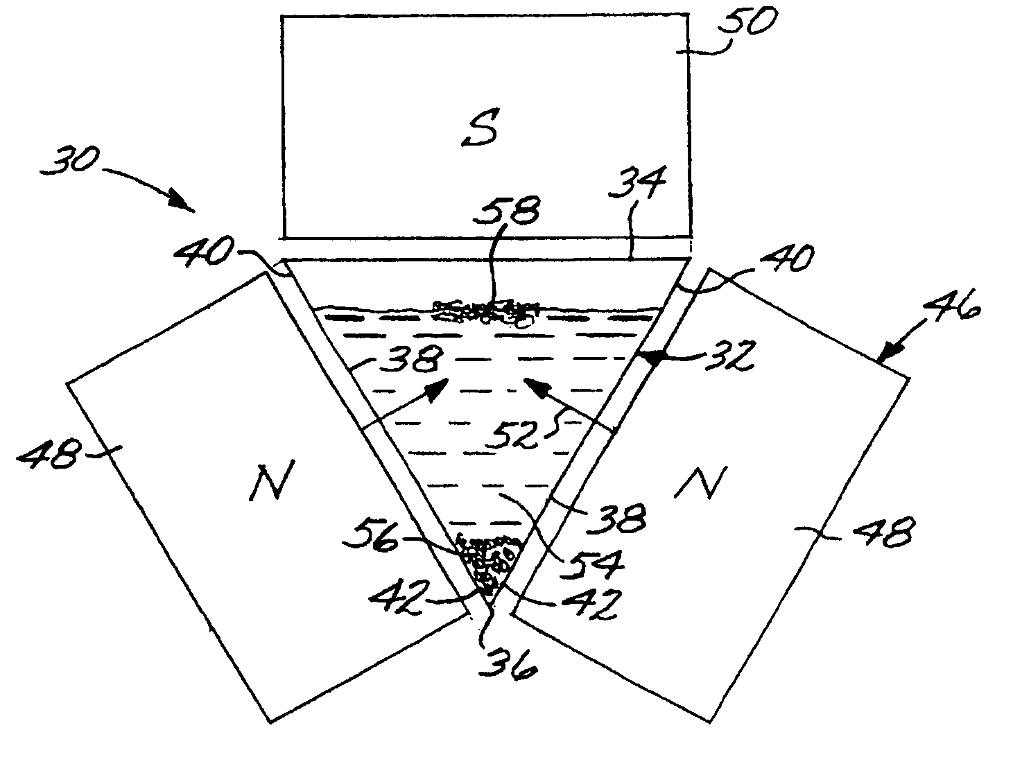
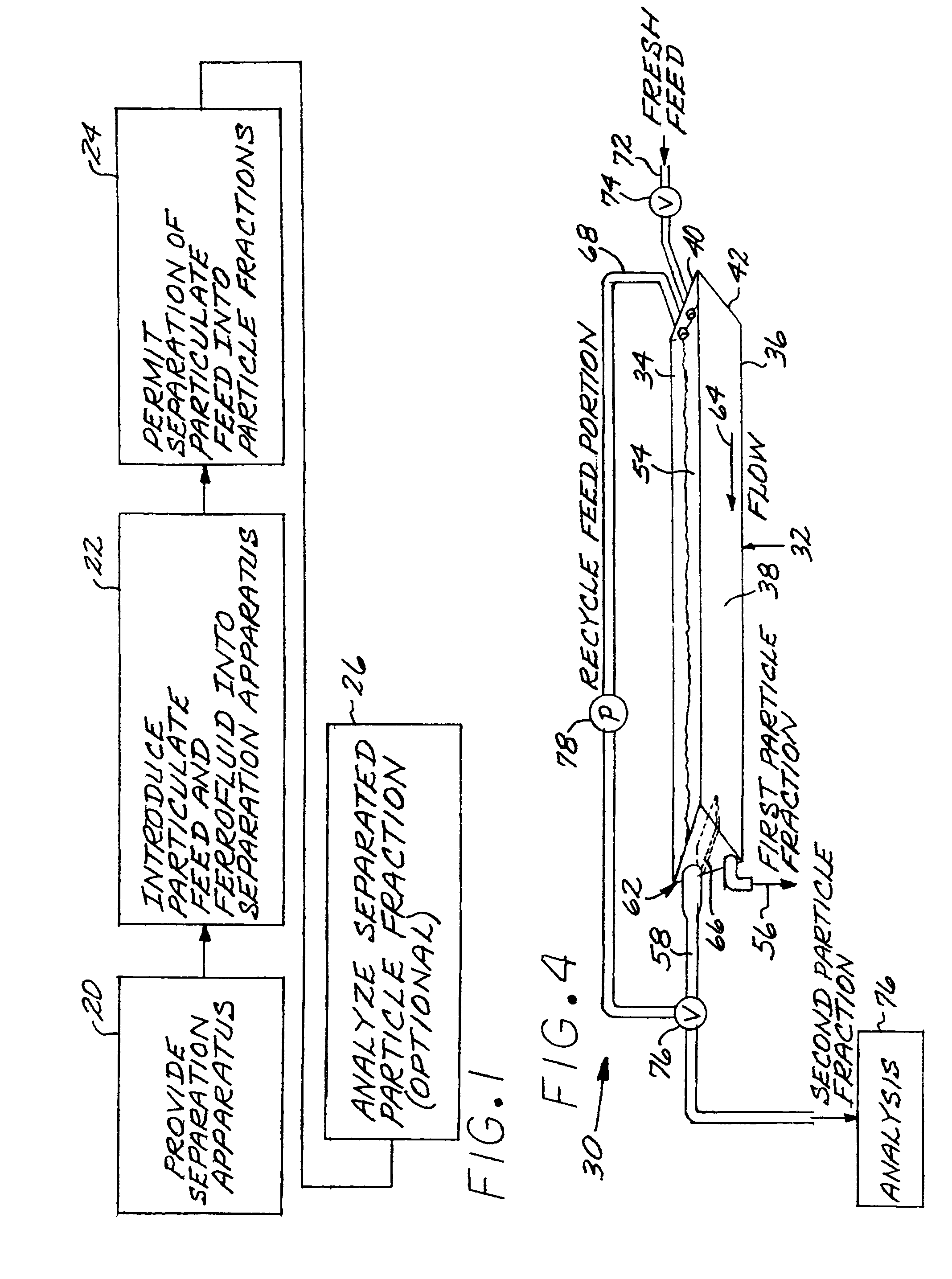
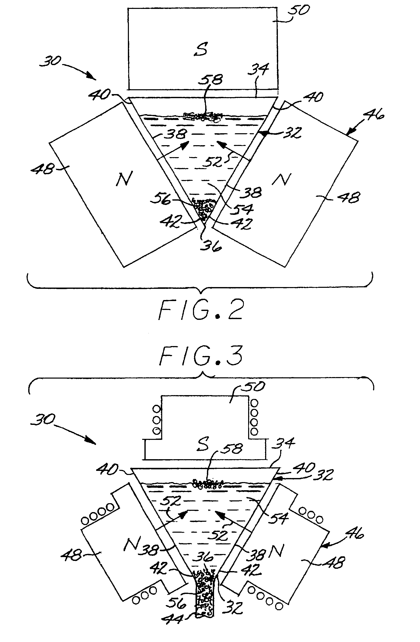
[0018]FIG. 1 depicts in block diagram form an embodiment of a method for separating a particulate feed comprising a first particle type and a second particle type. The method comprises first providing a separation apparatus 30. Three embodiments of the separation apparatus 30 are depicted in FIGS. 2–4. In each case, the separation apparatus 30 comprises a separation vessel 32 having a top 34 and a bottom 36. The separation vessel 32 includes inwardly sloping side walls 38. That is, there is a greater spacing between the side walls 38 at their top ends 40 than at their bottom ends 42. In the embodiment of FIG. 2, the bottom 36 of the separation vessel 32 is closed. In the embodiment of FIG. 3, the bottom 36 of the separation vessel 32 has a tube 44 extending downwardly therefrom. The separation vessels 32 of the embodiments of FIGS. 2 and 3 may be troughs that extend out of the plane of the illustration, or they may be conical (FIG. 2) or funnel-shaped (FIG. 3), or any other operable...


PUM


Abstract

A particulate feed comprising a first particle type and a second particle type is separated by providing a separation apparatus having a separation vessel having a top and a bottom, and wherein the separation vessel includes inwardly sloping side walls. A magnet structure has a first pole positioned exterior of and adjacent to each of the side walls of the separation vessel, and a second pole positioned above the separation vessel. A mixture of the particulate feed and a ferrofluid is introduced into the separation vessel, and the particulate feed is separated into a first particle fraction comprising a majority of the first particle type, which sinks in the separation vessel, and a second particle fraction comprising a majority of the second particle type which floats in the separation vessel.

Description

[0001]This invention relates to the separation of particle fractions from a particulate feed and, more particularly, to such a separation accomplished using ferrofluids and an applied magnetic field.BACKGROUND OF THE INVENTION[0002]Powder metallurgical processes offer an alternative to casting and casting-and-working for the production of metallic articles. In a powder metallurgical process, the alloy that is to constitute the article is first prepared in a fine-particle form. A mass of the alloy particulate is compacted to the required shape at elevated temperature with or without a binder. For example, hot isostatic pressing is a binderless process used to manufacture a number of aerospace and other types of parts. Where they can be used, powder metallurgical processes offer the advantages of a more-homogeneous microstructure in the final article, and reduced physical and chemical contaminants in the final article.[0003]The powder used in the powder metallurgical process is typica...

Claims


Application Information

Patent Timeline
Patent Type & Authority Patents(United States)
IPC IPC(8): B03B5/00B03C1/033B03C1/28B07C5/344
CPCB03C1/0332B03C1/288B03C1/32B03C2201/24B03C2201/18
Inventor ROTH, PAUL GREGORYHALTER, RICHARD FREDERICK
Owner GENERAL ELECTRIC CO
Why Eureka
Try Eureka