
Attachment means for facilitating user access to vehicle platforms

a technology for facilitating user access and vehicle platforms, which is applied in the direction of vehicle components, steps arrangement, supplementary fittings, etc., can solve the problems of personal injury, difficult to climb on or into vehicles, and tiring exercise, etc., and achieves the effect of convenient access

Inactive Publication Date: 2006-02-07
FOSTER ALLAN EUGENE
View PDF30 Cites 36 Cited by
  • Summary
  • Abstract
  • Description
  • Claims
  • Application Information

AI Technical Summary

Benefits of technology

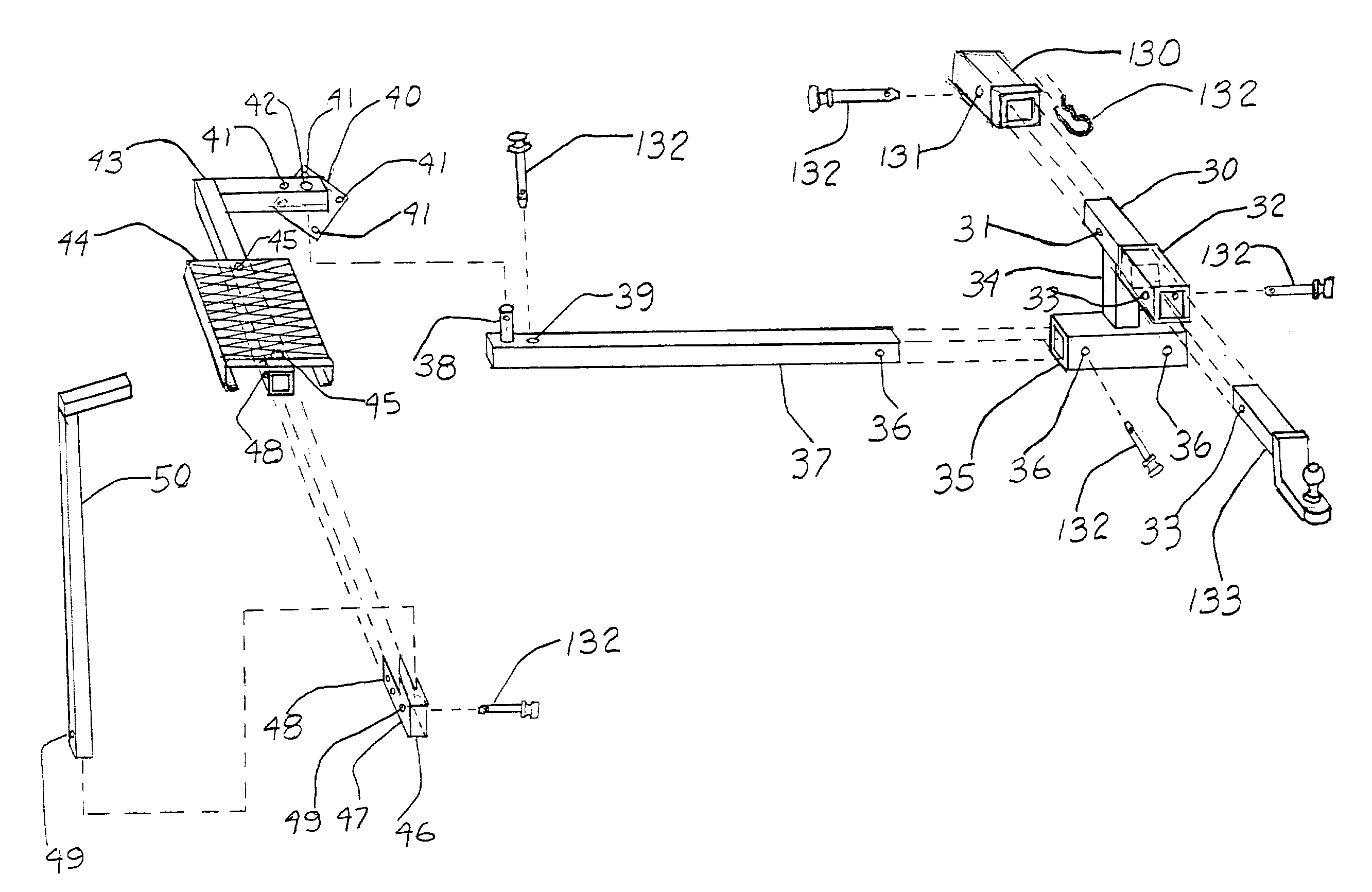
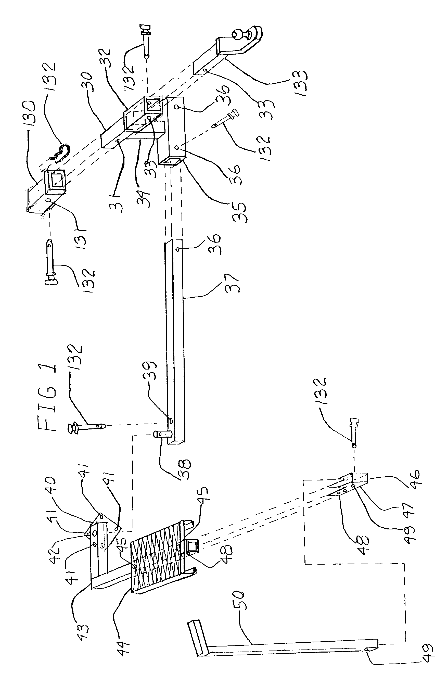
[0016]B)—a pivot pin and pivot pin extension bar assembly, which is attached to the “accessory receiver”, and hereafter is called a “pivot pin bar”. The pivot pin and pivot pin extension bar assembly consists firstly of an extension bar adapted to fit within the accessory receiver, and is secured thereto by means of a hitch pin. This extension bar is essentially parallel with the rear of the vehicle and normally below the vehicle bumper location. At the distal end of the extension bar is located a vertical pivot pin on which the pivot step can be rotated in a horizontal plane into it's several working positions and it's stowage position. Pivot pin bars fit into either the right or left receiver of the “accessory receiver”, giving flexibility of installing a pivot step on either side of the vehicle platform.
[0045]Yet another object of the invention is To provide a step position which will give easier access to a vehicle bumper, for entry into the rear of (for example a pickup truck with the tailgate up).

Problems solved by technology

These vehicles are often very difficult to climb on or into because of their height above the ground.
This exercise is time consuming, tiring, and sometimes embarrassing or unsafe.
Without the improved step attachment any one accessing a raised platform from the ground would have to do so in a cumbersome, awkward, and unsafe fashion, that could lead to personal injury.

Method used


Image

  • Attachment means for facilitating user access to vehicle platforms
  • Attachment means for facilitating user access to vehicle platforms
  • Attachment means for facilitating user access to vehicle platforms

Examples


Embodiment Construction

[0076]Detailed descriptions of the preferred embodiment are provided herein. It is to be understood, however, that the present invention may be embodied in various forms. Therefore, specific details disclosed herein are not to be interpreted as limiting, but rather as a basis for the claims and as a representative basis for teaching one skilled in the art to employ the present invention in virtually any appropriately detailed system, structure or manner.

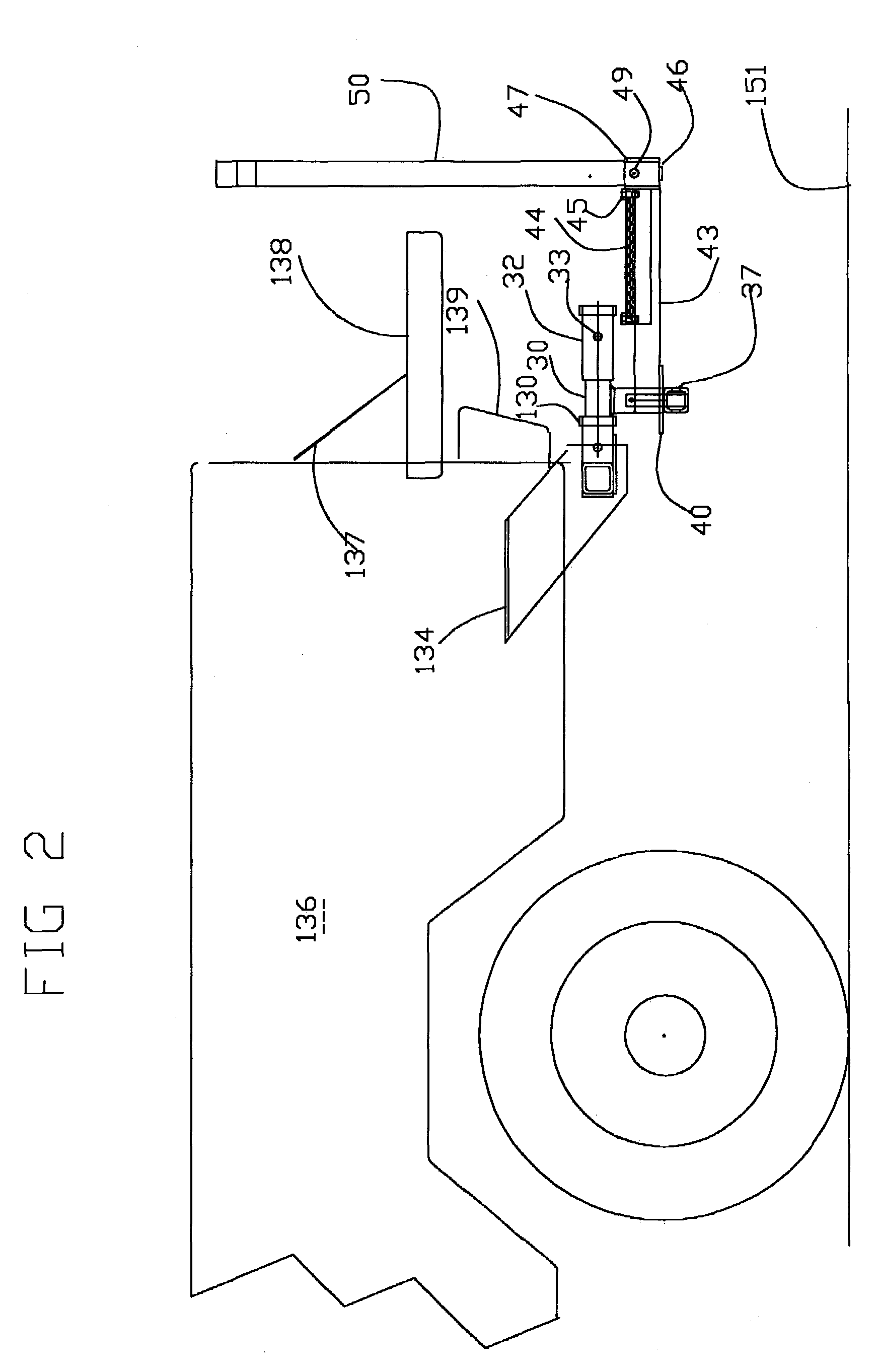
[0077]Turning first to FIG. 1 there is shown an isometric view of a rotatable step assembly with all it's components as mounted in the receiver of a conventional receiver type trailer hitch 130, and secured in place with a hitch pin and clip 132 in hole 131. An “accessory receiver” is shown comprising components 30 through 36 and is fabricated by welding or the like. The center receiver extension bar 30 is normally a solid member to support weight of a trailer or other platform being towed. Tubular member 32 is suitably fastened to t...


PUM


Abstract

Improved selectively rotatable multipositionable step attachment for a vehicle platform and the like for not only facilitating safe user access to the platform, for loading and unloading same, when the step attachment is in an operative position, but also when it is in a non operative or stowage position for facilitating additional use of the platform such as for towing another platform or for facilitating attachment of an auxiliary platform to the vehicle platform. The step attachment is generally made up of a support bar, a rotatable step tread of L-shaped configuration, a multiappatured index plate concentrically affixed to the outer end of either the support bar or the rotatable step tread, and a device to fasten the step assembly to the vehicle platform. Depending on the various requirements of the step attachment when being connected to a vehicle platform and the like, various mounting arrangements are provided.

Description

CROSS REFERENCE TO RELATED APPLICATIONS[0001]Not ApplicableSTATEMENT REGARDING FEDERALLY SPONSORED RESEARCH OR DEVELOPMENT[0002]Not ApplicableDESCRIPTION OF ATTACHED APPENDIX[0003]Not Applicable.ROTATABLE STEP ATTACHMENT[0004]This invention relates generally to the field of a step, having several working positions which can be achieved by rotating the step around a fixed pivot, and more specifically to a machine to assist a person entering into a vehicle or on a machine.HISTORY OF THE INVENTION[0005]This invention relates to any type of platform such as Pickup trucks, SUV's, and construction equipment, etc. where user access is required. These vehicles are often very difficult to climb on or into because of their height above the ground. My invention provides an improved selectively rotatable step attachment that is not only positionable in more than one working position, but also in a stowable position when the platform is being used for other purposes. Each position is easily lock...

Claims


Application Information

Patent Timeline
IPC IPC(8): B60R3/00B60R9/06
CPCB60R9/06B60R3/005
Inventor FOSTER, ALLAN EUGENE
Owner FOSTER ALLAN EUGENE
Learn More