Treatment device for tissue from living tissues

a technology of living tissues and treatment devices, which is applied in the field of therapeutic devices for treating living tissues, can solve the problems of inability to use, complex structure, and inability to maintain the integrity of the insulation structure, and achieve the effect of simple structure and improved durability of the electricity supply means

Inactive Publication Date: 2006-02-07
OLYMPUS CORP
View PDF12 Cites 459 Cited by
  • Summary
  • Abstract
  • Description
  • Claims
  • Application Information

AI Technical Summary

Benefits of technology

[0012]The object of the present invention is to provide a treatment device for a tissue from a living tissues, that can improve the durability of ...

Problems solved by technology

Here, since the two poles themselves must be insulated from each other while supplying electricity, the insulation structure is complicated.
Such a structure is very complicated, a...

Method used


Image

  • Treatment device for tissue from living tissues
  • Treatment device for tissue from living tissues
  • Treatment device for tissue from living tissues

Examples


first embodiment

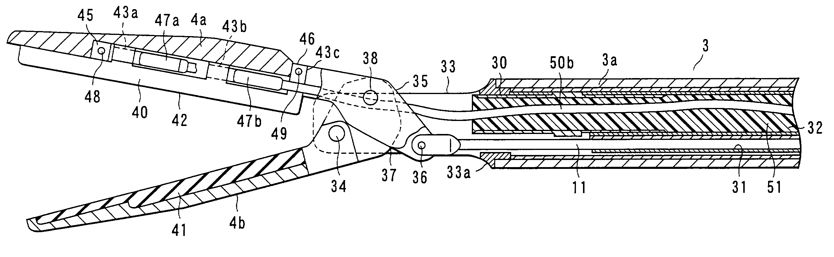
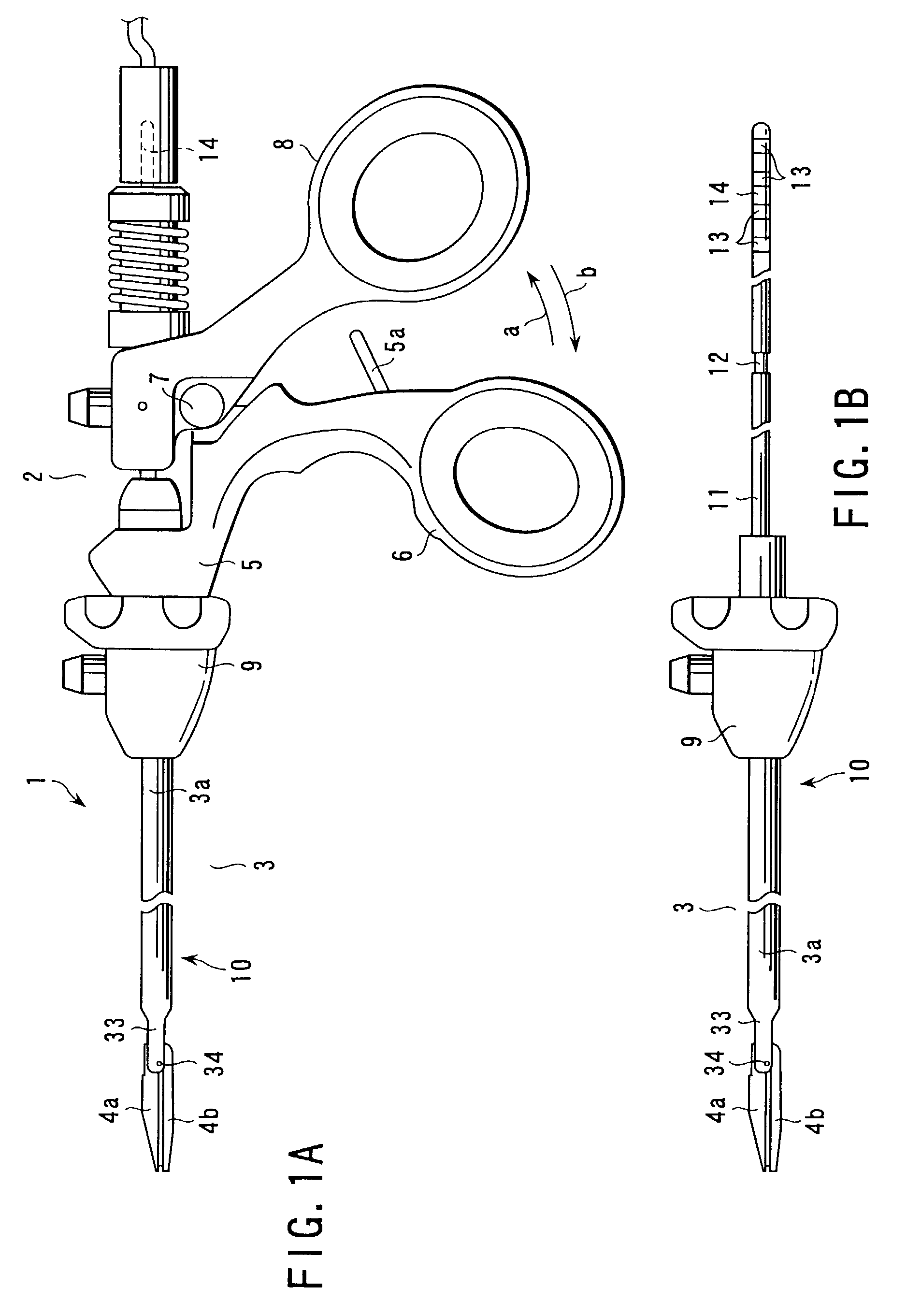
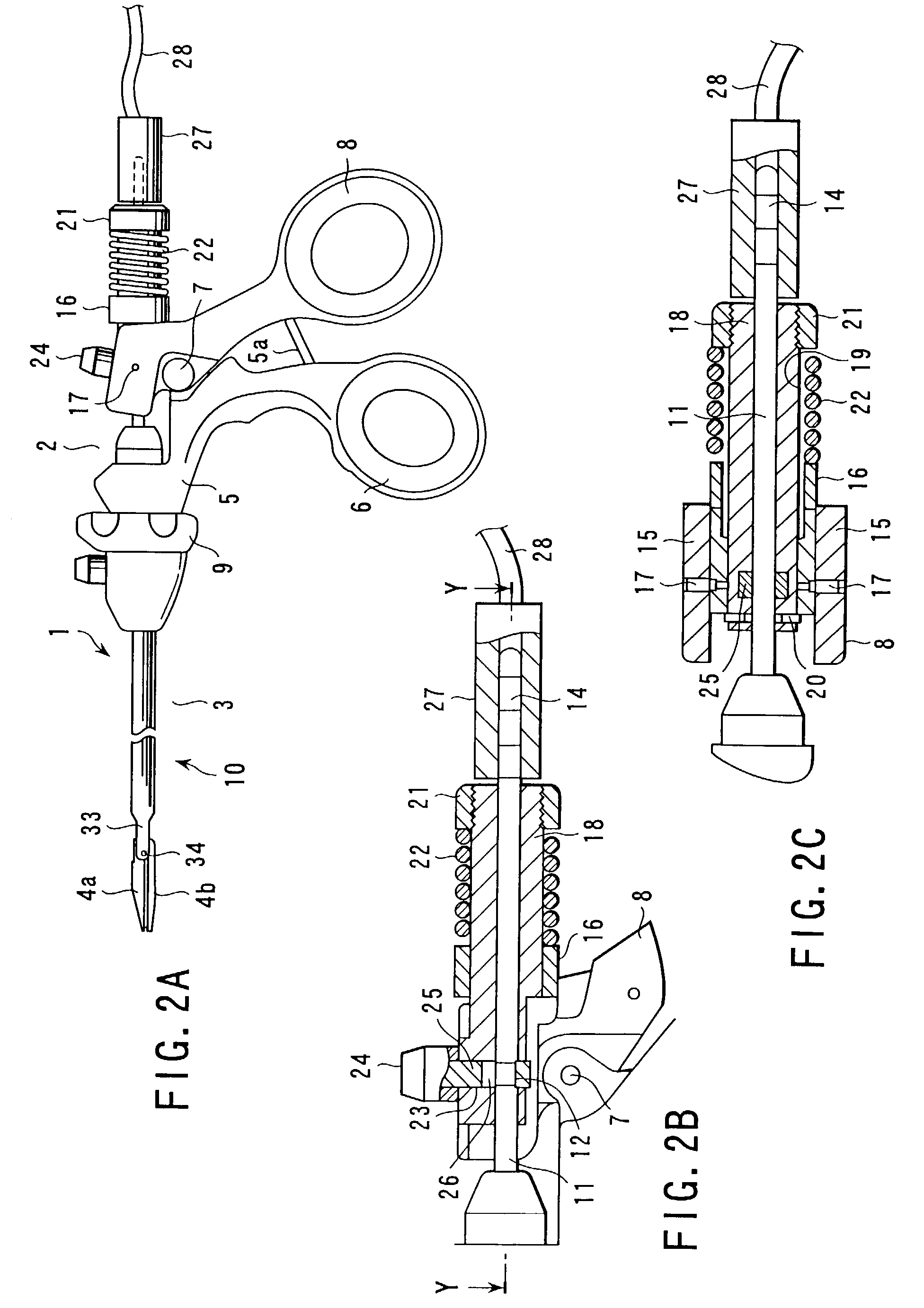
[0063]FIGS. 1A to 5F illustrates the present invention. As can be seen in FIGS. 1A and 1B, thermal-coagulation cutting forceps 1 used for an operation using an endoscope, serving as a therapeutic device for a living tissue, include an operating portion 2, a slender insertion portion 3 provided for the operating portion 2 and first and second jaws 4a and 4b set in pair, that open / close against each other, provided in the distal end portion of the insertion portion 3.

[0064]The insertion portion 2 includes a operating portion main body 5, a stationary handle 6 provided to be integral with the operating portion main body 5, and a movable handle 8 provided to be rotatable on the main body 5, around the pivotal shaft 7. The operating portion main body 5 is provided with a detachable forceps unit 10, such that the insertion portion 3 can be rotated with a rotation operating portion 9 around the axial center.

[0065]The insertion portion 3 is made of a small-diameter pipe 3a, and a drive shaf...

fifth embodiment

[0123]A metal pipe 106 is inserted to each one of the adhered portions of the resin tube 105, that is, between the first heat insulation member 100 situated on the proximal end side of the first jaw 4a and the second heat insulation member 101, and in the distal end side of the channel formed in the drive shaft 11. In the portions where these metal pipes 106 are inserted, the respective portion of the resin tube 105 is reduced in size by the thickness of the metal pipe 106. Further, the resin tube 105 is pierced through the two metal pipes 106. Here, as in the case of the fifth embodiment, the cable that serves as the electricity supply means is sealed in the resin tube 105.

[0124]With the above-described structure, the resin tube 105 is fixed by the metal pipes 106. Thus, the fixation force on the cable is more strong as compared to the case where the drive shaft 11 and the resin tube 105 are adhered together.

[0125]In this embodiment, a plurality of single-wire cables are employed a...


PUM


Abstract

A pair of openable/closable jaws, an insertion section configured to support the pair of jaws, an operation section configured to open/close the pair of jaws, a heat generating element provided in a jaw, that generates heat by supply of electricity, electricity supply means configured to supply electricity to the heat generating element, and damage protecting means for protecting the electricity supply means from being damaged, are provided.

Description

CROSS-REFERENCE TO RELATED APPLICATIONS[0001]This application is based upon and claims the benefit of priority from the prior Japanese Patent Applications No. 2001-262132, filed Aug. 30, 2001; No. 2002-135601, filed May 10, 2002; and No. 2002-137104, filed May 13, 2002, the entire contents of all of which are incorporated herein by reference.BACKGROUND OF THE INVENTION[0002]1. Field of the Invention[0003]The present invention relates to a therapeutic device for treating a tissue of a living tissues, that can coagulate and cut the tissue while holding it.[0004]2. Description of the Related Art[0005]Living tissue therapeutic devices that can coagulate and cut a tissue while holding it generally include a pair of holding members for holding a tissue of a living tissues. In these devices, a heat generator is provided on one or both sides of the holding members and the heat generator is turned on to generate heat while holding a tissue with the pair of the holding members so as to coagul...

Claims


Application Information

Patent Timeline
IPC IPC(8): A61B18/14A61B18/08
CPCA61B18/085
Inventor IIDA, KOJI
Owner OLYMPUS CORP
Why Eureka
Try Eureka