Four-way interlock system and bypass transfer switch employing the same

a transfer switch and interlocking system technology, applied in the direction of contact mechanisms, switchgear with withdrawn carriage, contact, etc., can solve the problems of adding time and complexity to the bypass operation, and the added time and complexity of the kirk® key bypass interlock scheme is unacceptabl

Active Publication Date: 2006-02-07
EATON INTELLIGENT POWER LIMITED
View PDF14 Cites 57 Cited by
  • Summary
  • Abstract
  • Description
  • Claims
  • Application Information

AI Technical Summary

Benefits of technology

The present invention provides an interlock system that meets specific requirements for use in bypass transfer switches. This system helps ensure safe operation and reliability during power failures or other emergency situations.

Problems solved by technology

The technical problem addressed in this patent text relates to improving the design of bypass transfer switches used in situations requiring alternative power sources, particularly in cases where failure of the main source occurs frequently. Current methods require complex and time-consuming procedures to achieve proper synchronization between the backup and main sources, making rapid switching necessary in critical settings. There is a need for a simpler solution to allow for faster and more reliable connections in the event of a power outage.

Method used


Image

  • Four-way interlock system and bypass transfer switch employing the same
  • Four-way interlock system and bypass transfer switch employing the same
  • Four-way interlock system and bypass transfer switch employing the same

Examples


Embodiment Construction

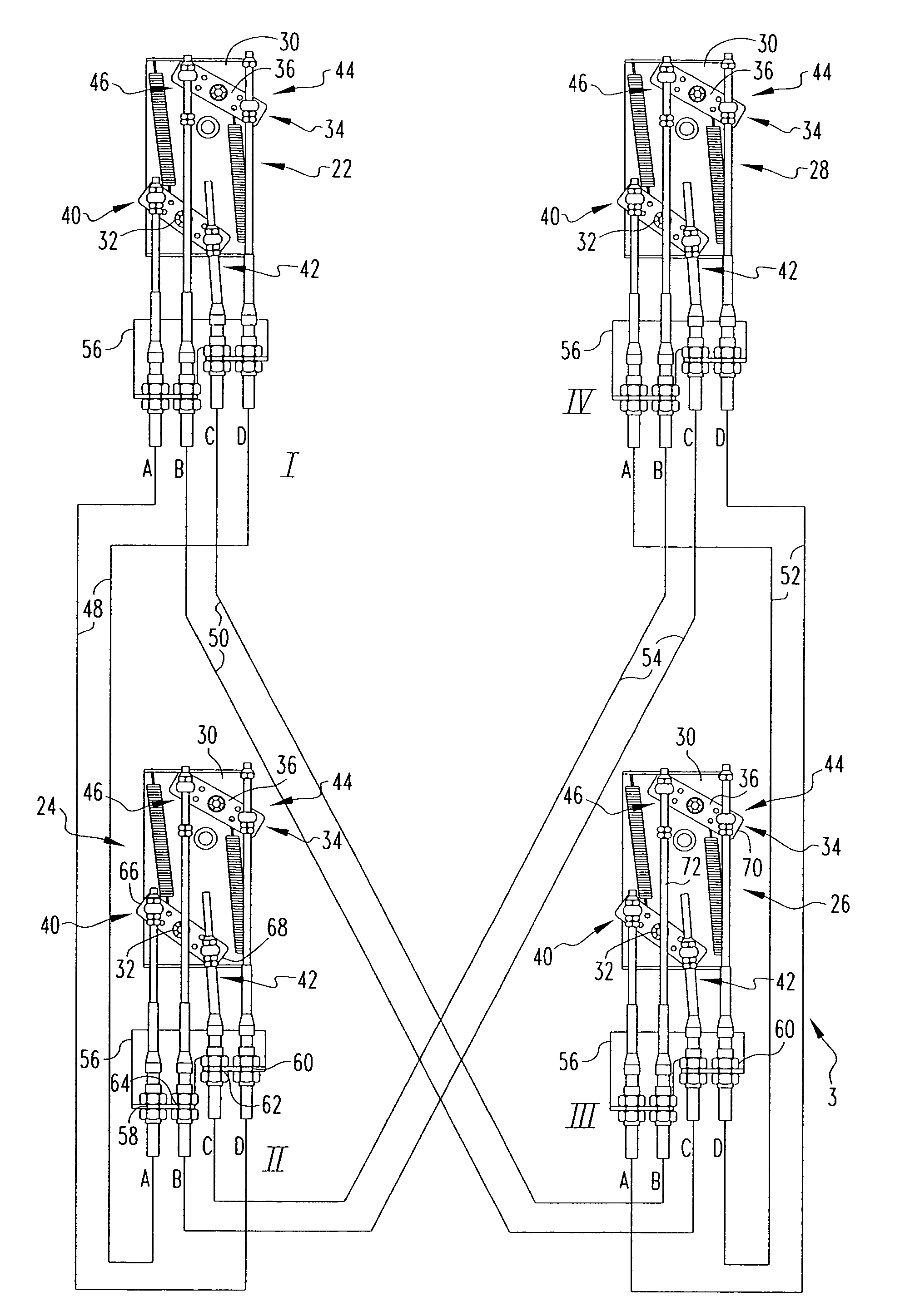
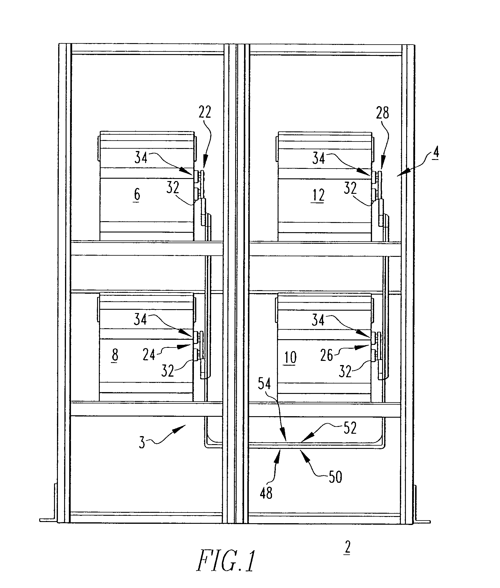
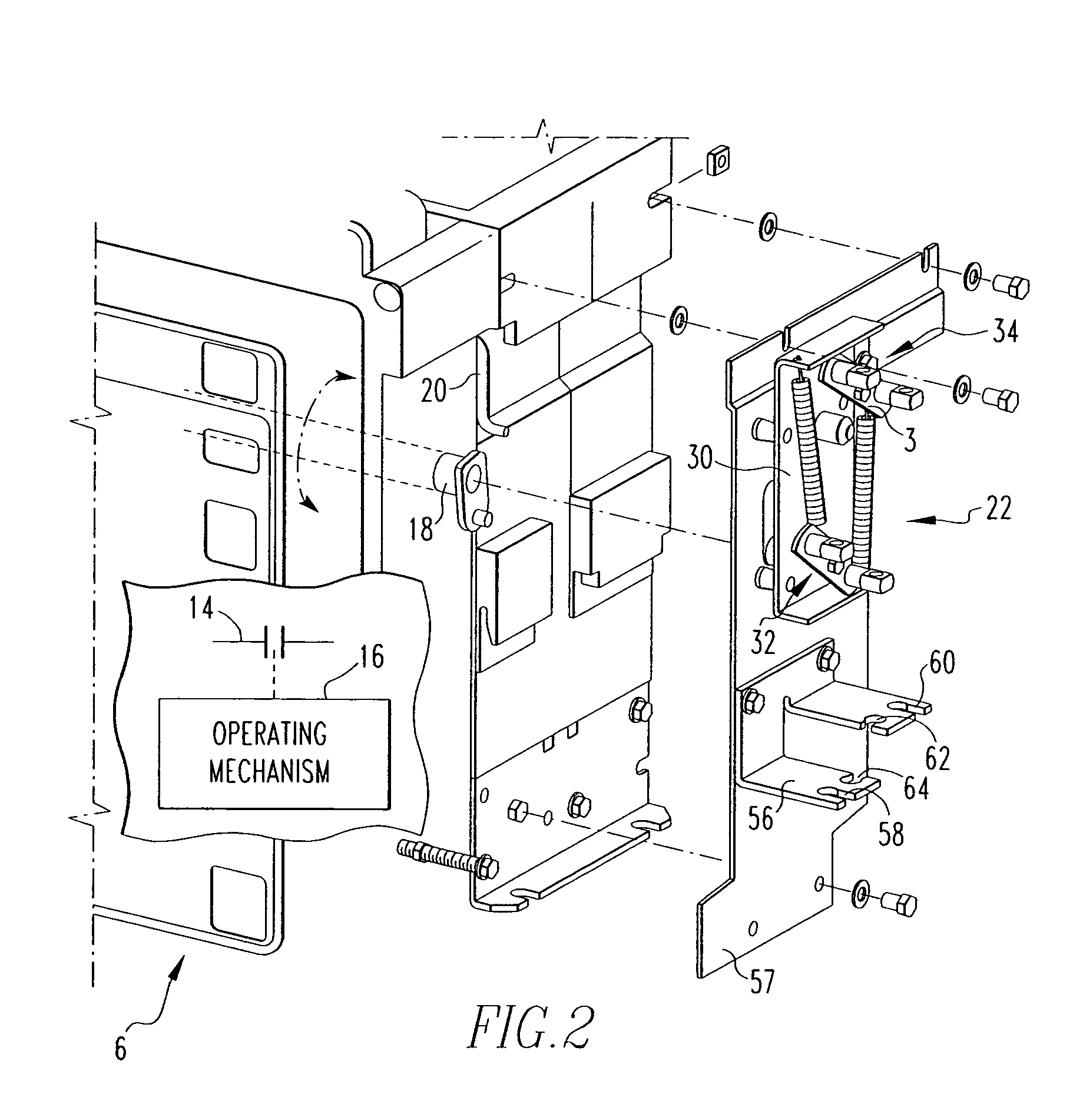
[0023]Directional phrases used herein, such as, for example, left, right, clockwise, counterclockwise and derivatives thereof, relate to the orientation of the elements shown in the drawings and are not limiting upon the claims unless expressly recited therein.

[0024]As employed herein, the term “fastener” refers to any suitable connecting or tightening mechanism expressly including, but not limited to, screws, bolts and the combinations of bolts and nuts (e.g., without limitation, lock nuts) and bolts, washers and nuts.

[0025]As employed herein, the statement that two or more parts are “coupled” together shall mean that the parts are joined together either directly or joined through one or more intermediate parts.

[0026]As employed herein, the term “linkage” refers to any known or suitable mechanism (e.g., without limitation, a cable; a wire; a chain; a number of interconnected links; a rigid member) for interconnecting one component to another in order to provide mechanical communica...


PUM


Abstract

An interlock system is for a bypass transfer switch including first, second, third and fourth circuit breakers. First, second, third and fourth interlock assemblies each include a mounting bracket coupled on or proximate to a corresponding one of the circuit breakers, a transmitting member disposed on the mounting bracket and coupled to the poleshaft of the operating mechanism of the corresponding one of the circuit breakers, and a receiving mechanism disposed on the mounting bracket and structured to engage and actuate the circuit breaker trip lever in response to a trip condition. The transmitting member and receiving mechanism each include primary and secondary connections. A plurality of linkages are adapted to interconnect the connections among the circuit breakers in order to provide a predetermined automatic bypass interlock mechanism, without requiring a separate manual locking device.

Description


Claims


Application Information

Patent Timeline
Owner EATON INTELLIGENT POWER LIMITED
Why Eureka
Try Eureka