Method and apparatus for transfer control and undervoltage detection in an automatic transfer switch

a technology of automatic transfer switch and transfer control, which is applied in the direction of dc source parallel operation, emergency power supply arrangement, transportation and packaging, etc., can solve the problems of catastrophic short circuit, potential backfeed problem, and the possibility of shock to the power pin on the end of the cord, so as to prevent undesirable cross-conduction and prevent undesirable cross-conduction

Inactive Publication Date: 2005-04-12
VERTIV CORP
View PDF7 Cites 54 Cited by
  • Summary
  • Abstract
  • Description
  • Claims
  • Application Information

AI Technical Summary

Benefits of technology

One feature of the present invention is a relay sequencing scheme that prevents undesirable cross-conduction between the two input AC sources of an automatic transfer switch. Cross-conduction is caused by contact arcing that starts when the relays of one source are opened and continues after the relays of a second source are closed. The present invention solves this problem by placing an extra set of relays in series with an upstream of the main transfer relay. The extra relays independently control switching of the inputs. Because the inputs are switched independently, a time delay may be introduced between the opening of the first set of contacts and the closing the other set, thereby allowing sufficient time for the arcing to stop and preventing the undesirable cross-conduction between the two sources.

Problems solved by technology

However, rapid relay switching creates a possible shoot-through problem, i.e., an arc will form between the opening contacts, and if this arc is still conducting when the closing contacts close, a current path is created between the two input sources, shorting them together through the arc.
This creates a potential backfeed problem, i.e., if one of the inputs is unplugged, a person touching the power pins on the end of the cord could be shocked by power coming from the other source.
Furthermore, if both circuits are powered, a catastrophic short circuit would result.
These safety problems render the system disclosed in the '163 Patent unacceptable under UL safety standard UL1950.
An additional challenge facing designers and users of automatic transfer switches is detecting a failure of the primary source, so that a transfer to the secondary source can be initiated.
Most of the known techniques for detecting the level of an AC signal by converting it to a DC signal require long time constant filters to remove the AC component of the signal.
These long time constant filters have long delays that are unacceptable in a transfer switch application, which must detect an AC signal failure in a quarter cycle or less.
Because the source voltage is nearly zero during this portion of the cycle, it is difficult to differentiate between the normal waveform zero crossing and a source failure.
If he voltage has not risen, a failure has occurred.
In addition to the undesirable delay, an additional disadvantage of this technique is that it requires a CPU, with the associated complexity, noise and reliability problems.

Method used


Image

  • Method and apparatus for transfer control and undervoltage detection in an automatic transfer switch
  • Method and apparatus for transfer control and undervoltage detection in an automatic transfer switch
  • Method and apparatus for transfer control and undervoltage detection in an automatic transfer switch

Examples


Embodiment Construction

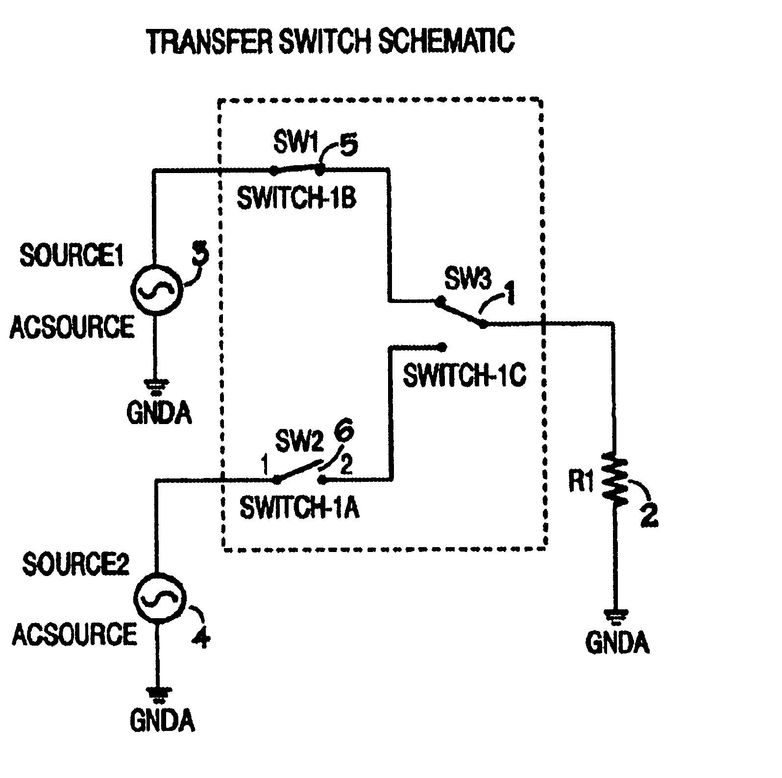
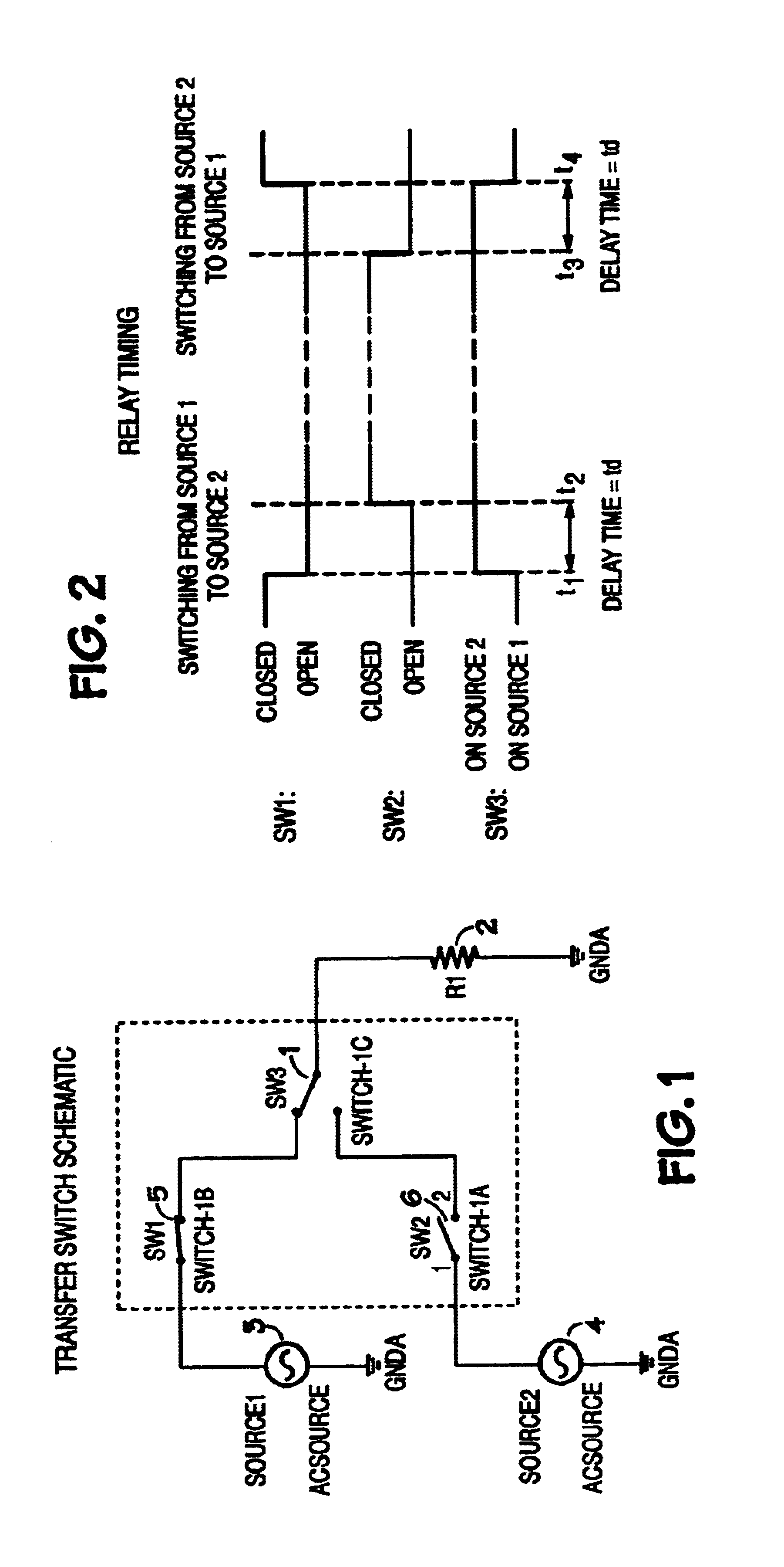
An automatic transfer switch in accordance with the present invention is illustrated in FIG. 1. Automatic transfer switch 7 connects first alternating current (“AC”) voltage source 3 and second AC voltage source 4 to load 2. For purposes of the following discussion, first AC voltage source 3 will be referred to as the primary source and AC voltage source 4 will be referred to as the secondary source. Under normal conditions, i.e., when primary source 3 is available, transfer switch 7 will connect primary source 3 to load 2. If primary source 3 fails, transfer switch 7 will automatically and rapidly connect second source 4 to load 2 to prevent disruption of power to load 2.

Automatic transfer switch 7 comprises switch 1, illustrated as a form C relay, as the primary transfer element. To minimize power disruption to the load, it is desirable that switch 1 switch as rapidly as possible upon failure of the normal source. However, rapid switching of switch 1 creates a potential shoot thro...


PUM


Abstract

An automatic transfer switch is disclosed that features a novel arrangement for detecting a failure of the power source as well as a novel arrangement for preventing cross-conduction between the first and second signal sources during a rapid transfer.

Description

BACKGROUND OF THE INVENTIONThe simplest mechanical automatic transfer switch comprises a single form C relay. It is desirable to have the relay switch quickly to minimize the power disruption to the load. However, rapid relay switching creates a possible shoot-through problem, i.e., an arc will form between the opening contacts, and if this arc is still conducting when the closing contacts close, a current path is created between the two input sources, shorting them together through the arc.This problem was addressed in, for example, U.S. Pat. No. 4,811,163 which discloses the use of solid state snubbers in parallel with two mechanical form A or form B relays, with the relays used to accomplish the transfer. The arc is quenched by the solid state snubbers in parallel with the opening switch contact. Conversely, the present invention uses a relay in series with the contact for arc quenching rather than a parallel snubber. Furthermore the control circuit timing used in the present inv...

Claims


Application Information

Patent Timeline
Patent Type & Authority Patents(United States)
IPC IPC(8): H02J9/06
CPCH02J9/061H02J2009/068H02J9/068
Inventor HOHRI, ELLIOT BROOKS
Owner VERTIV CORP
Why Eureka
Try Eureka