Photoelectric conversion apparatus and image sensing system using the same

a technology of photoelectric conversion apparatus and image sensing system, which is applied in the direction of television system, radio frequency control device, instruments, etc., can solve the problem of increasing the parasitic capacitance of the common signal line, and achieve the effect of high speed

Inactive Publication Date: 2009-06-30
CANON KK
View PDF43 Cites 54 Cited by
  • Summary
  • Abstract
  • Description
  • Claims
  • Application Information

AI Technical Summary

Benefits of technology

[0007]The present invention provides a photoelectric conversion apparatus that includes block lines and that is capable of performing a resetting operation at high speed.

Problems solved by technology

Accordingly, the number of switching transistors has increased (that is, total source capacitance has increased) and the capacitance of a signal line has increased, resulting in an increased parasitic capacitance of the common signal line.

Method used


Image

  • Photoelectric conversion apparatus and image sensing system using the same
  • Photoelectric conversion apparatus and image sensing system using the same
  • Photoelectric conversion apparatus and image sensing system using the same

Examples


first exemplary embodiment

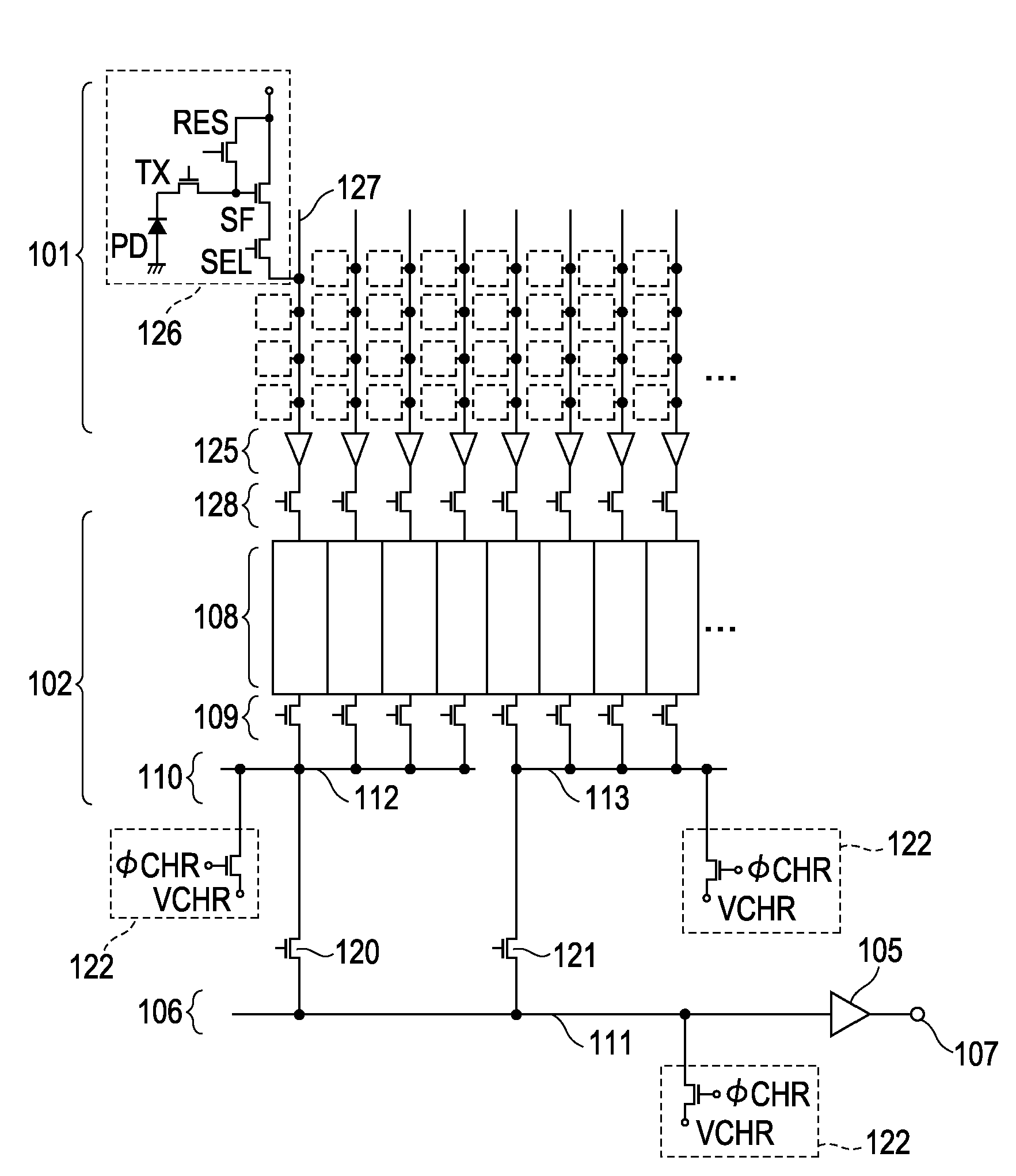
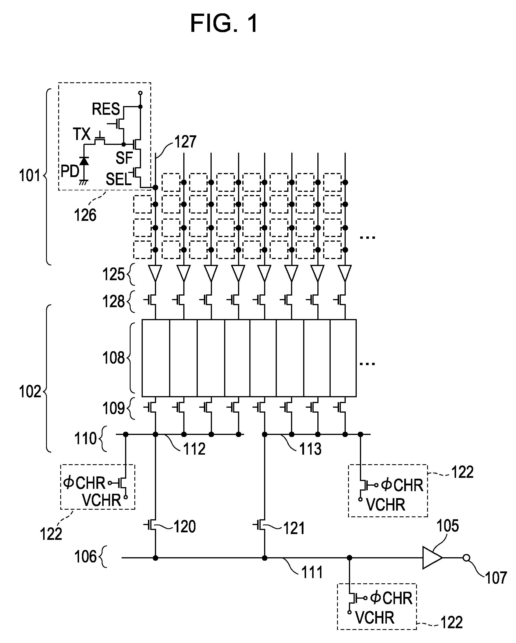
[0031]Referring to FIG. 1, a configuration of a first exemplary embodiment will be described in detail. In FIG. 1, a path from a pixel unit 101 through a read unit 102 (for example, the first read unit 102a shown in FIG. 6) to an output terminal 107 (for example, the first output terminal 107a shown in FIG. 6) is shown.

[0032]In the pixel unit 101, pixels 126 are arranged in a matrix. Each of the pixels 126 includes a photodiode PD, which is a photoelectric conversion element, a transfer switch TX used to transfer a charge of the photodiode PD, and a resetting switch RES used to reset an active region to which the charge is transferred. Each of the pixels 126 further includes a MOSFET (SF) used to output a potential obtained in accordance with the charge, and a switch SEL used to select a corresponding pixel. Note that this configuration is merely an example. The pixels 126 are connected to corresponding vertical signal lines 127 arranged in a columnar direction. Amplifier units 125 ...

second exemplary embodiment

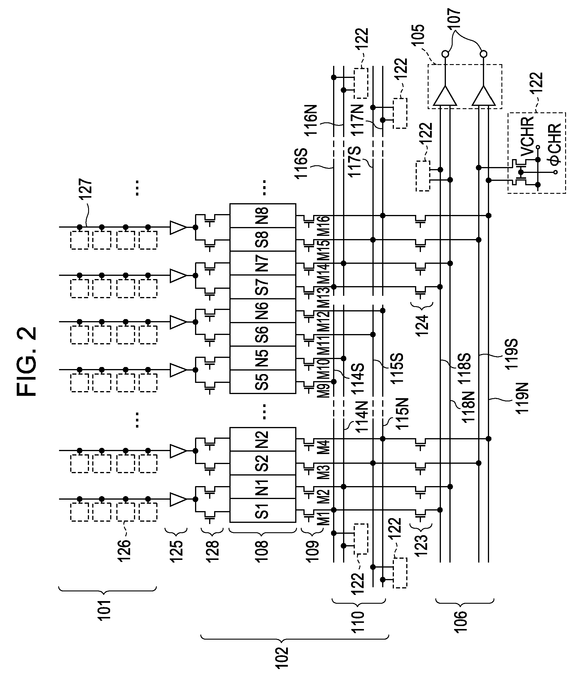
[0035]A photoelectric conversion apparatus according to a second exemplary embodiment is different from that according to the first exemplary embodiment in that four pairs of block lines and two pairs of common signal lines are arranged. With this configuration, signals having reduced noise components may be obtained and, therefore, a high-quality image may be obtained. Furthermore, because a pair of common signal lines 118 and a pair of common signal lines 119 are provided, the number of block lines and the number of switches connected to each of the pairs of common signal lines are reduced, resulting in reduced capacitances of the common signal lines. Similarly, because pairs of block lines 114 to 117 are provided, capacitances of the block lines are reduced. Accordingly, a reading operation faster than that of the first exemplary embodiment may be performed.

[0036]Referring to FIG. 2, the configuration of the second exemplary embodiment will be described in detail. A block line un...

third exemplary embodiment

[0044]In a third exemplary embodiment, as shown in FIG. 3, the number of resetting units connected to common signal lines of the third exemplary embodiment is larger than the number of resetting units connected to the common signal line of the second exemplary embodiment. In FIG. 1, the single resetting unit is connected to the common signal line. However, in FIG. 3, resetting units are connected to each of the common signal lines at a first end thereof in the vicinity of an amplifier circuit 105 and at a second end thereof opposite to the first end. With this configuration, when compared with the second exemplary embodiment, resetting operations are more readily performed and a signal reading operation is performed at higher speeds. Particularly, because a plurality of resetting units are separately provided for each common signal line, high-speed resetting operations are performed.


PUM


Abstract

A photoelectric conversion apparatus includes a pixel unit having a plurality of pixels arranged in a matrix, a plurality of block lines to which signals are supplied from the pixels, transfer switches used to supply the signals from the block lines to a common signal line, and a driving circuit configured to drive the pixels, the block lines, and the transfer switches. The block lines have resetting units used to reset potentials of the block lines. With this configuration, a signal reading operation is performed at high speed in the photoelectric conversion apparatus.

Description

BACKGROUND OF THE INVENTION[0001]1. Field of the Invention[0002]The present invention relates to photoelectric conversion apparatuses, and particularly relates to a read circuit of a photoelectric conversion apparatus.[0003]2. Description of the Related Art[0004]In general, photoelectric conversion apparatuses are used in digital still cameras. For example, photoelectric conversion apparatuses employing CCD sensors or MOS photoelectric conversion apparatuses are typically used. Such a MOS photoelectric conversion apparatus includes a pixel unit including basic cells (pixels) having photoelectric conversion elements such as photodiodes, the basic cells being arranged in a plane, a holding unit that holds signals transmitted from the pixel unit, and a common signal line (horizontal signal line) used to output the signals supplied from the holding unit to an external device.[0005]Improvements have been made to photoelectric conversion apparatuses to increase the number of pixels and to...

Claims


Application Information

Patent Timeline
Patent Type & Authority Patents(United States)
IPC IPC(8): H04N3/14H01L27/00H04N5/335H01L27/146H01L31/10H04N5/374H04N5/376
CPCH04N3/155H04N5/3577H04N5/374H04N5/378H04N25/617H04N25/76H04N25/75
Inventor KIKUCHI, SHINKOIZUMI, TORU
Owner CANON KK
Why Eureka
Try Eureka