Dynamic load shedding system for a standby generator

a technology of dynamic load shedding and standby generator, which is applied in the direction of emergency power supply arrangement, process and machine control, instruments, etc., can solve the problems of exceeding the rating limit of the standby generator, limiting the types of appliances connected to the standby generator, and drawing a significant amount of power

Active Publication Date: 2011-12-08
BRIGGS & STRATTON LLC
View PDF67 Cites 55 Cited by
  • Summary
  • Abstract
  • Description
  • Claims
  • Application Information

AI Technical Summary

Benefits of technology

Any time during the supply of power by the standby generator or at any other time, the user can selectively reassign the priority values to each of the electric loads to modify the order in which the electric loads are disconnected from the generator. In one embodiment, the transfer switch control unit includes a user interface that allows the user to either select one of a plurality of predefined priority assignment programs or assign priority values to each electric loa

Problems solved by technology

Since the power supply by the standby generator is limited by the size of the generator, the amperage rating of the generator can limit the types of and number of appliances that are connected to the standby generator during power outages.
As an

Method used


Image

  • Dynamic load shedding system for a standby generator
  • Dynamic load shedding system for a standby generator
  • Dynamic load shedding system for a standby generator

Examples


Embodiment Construction

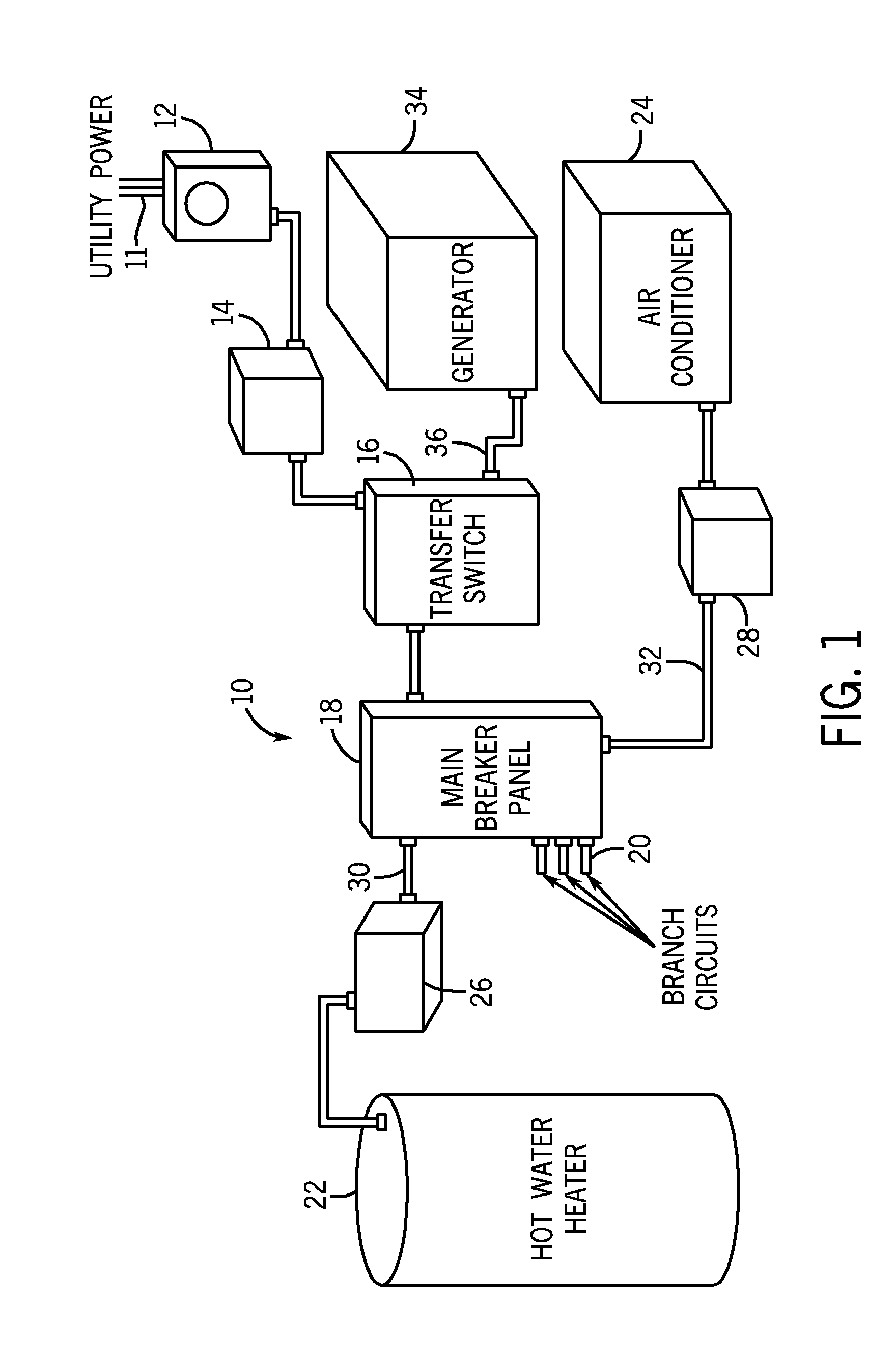
FIG. 1 depicts a load management system 10. The load management system 10 includes a connection to a main power supply 11 through a meter 12. The power supply from the meter 12 is fed through an optional service disconnect switch 14 to a transfer switch 16. The transfer switch 16 carries out a series of functions, as will be described below and can also be referred to as a load-management controller. Throughout the following disclosure, the term “transfer switch” will be utilized with the understanding that the transfer switch 16 could also be referred to as a load-management device.

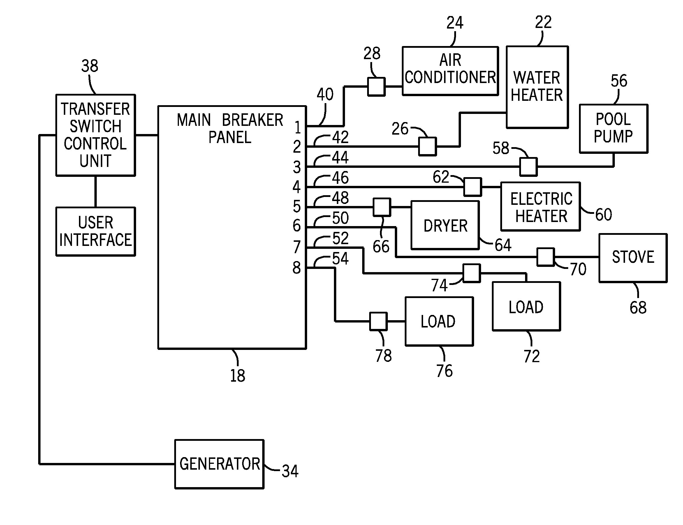
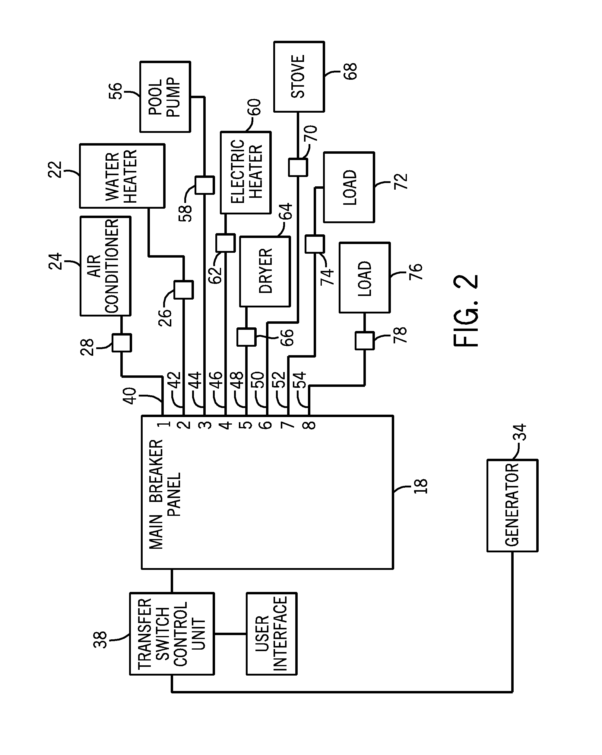
The transfer switch 16 feeds electrical power to a main breaker panel 18 for the residence. The main breaker panel 18 includes a series of individual branch circuits 20 to provide electrical power to normal loads included in a residence, such as the lights, power outlets, etc.

In addition to the branch circuits 20, several high power consumption loads, such as a hot water heater 22 and air conditioner 24,...


PUM


Abstract

A method and system for managing electrical loads on a standby generator. The method includes utilizing a transfer switch control to selectively shed loads each associated with one of a series of priority circuits. Priority values are initially assigned to each of the electric loads based upon the initial hard-wired connection of the electric loads to a main breaker panel during set up. The control unit of a transfer switch allows the user to reassign priority values to each of the electric loads based upon a user preference. The control unit includes one or more predefined priority assignment programs that can be selected to modify the priority values assigned to the electric loads.

Description

BACKGROUND OF THE INVENTIONThe present disclosure generally relates to a load shedding system. More specifically, the present disclosure relates to a load shedding system for selectively shedding the load applied to a standby generator.When there is a power outage, backup power may be provided by a standby generator. In some cases, the standby generator is started automatically after detection of the power outage. A standby generator that is started automatically usually requires an automatic transfer switch to connect electrical loads to the generator rather than from the power supply. A combination of a standby generator and an automatic transfer switch is generally installed by trained personnel.Since the power supply by the standby generator is limited by the size of the generator, the amperage rating of the generator can limit the types of and number of appliances that are connected to the standby generator during power outages. As an example, large appliances such as air condi...

Claims


Application Information

Patent Timeline
IPC IPC(8): H02J3/14
CPCH02J3/14H02J9/08Y04S20/248Y02B70/3291Y04S20/222Y02B70/3225Y02B70/30Y04S20/20H02J2310/60
Inventor BATZLER, BRANDON M.STAIR, KENNY J.LIM, SIE TEONG
Owner BRIGGS & STRATTON LLC
Why Eureka
Try Eureka