Image reading apparatus

Inactive Publication Date: 2006-02-07
CANON KK
View PDF5 Cites 6 Cited by
  • Summary
  • Abstract
  • Description
  • Claims
  • Application Information

AI Technical Summary

Benefits of technology

[0010]The present invention has been made in consideration of the above problems, and has as its object to provide an image reading apparatus in which image reading (scan flow

Problems solved by technology

Since the position for reading the conveyed original is set above the scan flow glass member arranged on the same plane as that o

Method used


Image

  • Image reading apparatus
  • Image reading apparatus
  • Image reading apparatus

Examples


first embodiment

[First Embodiment]

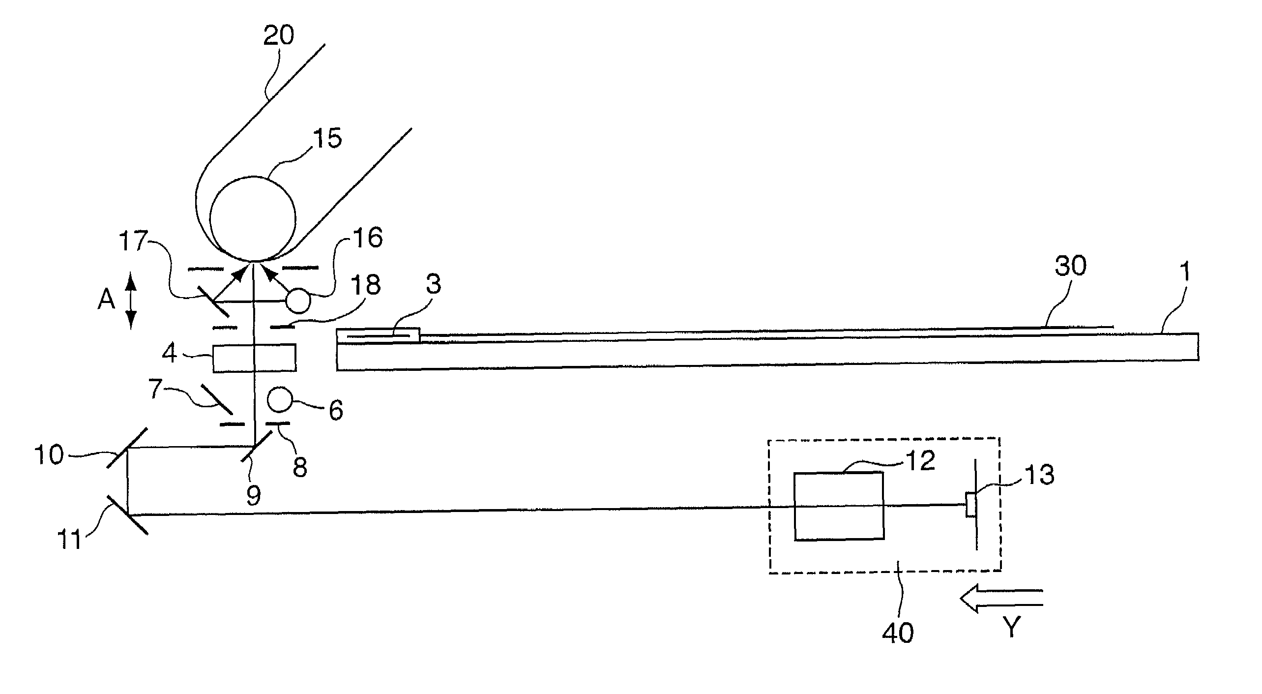
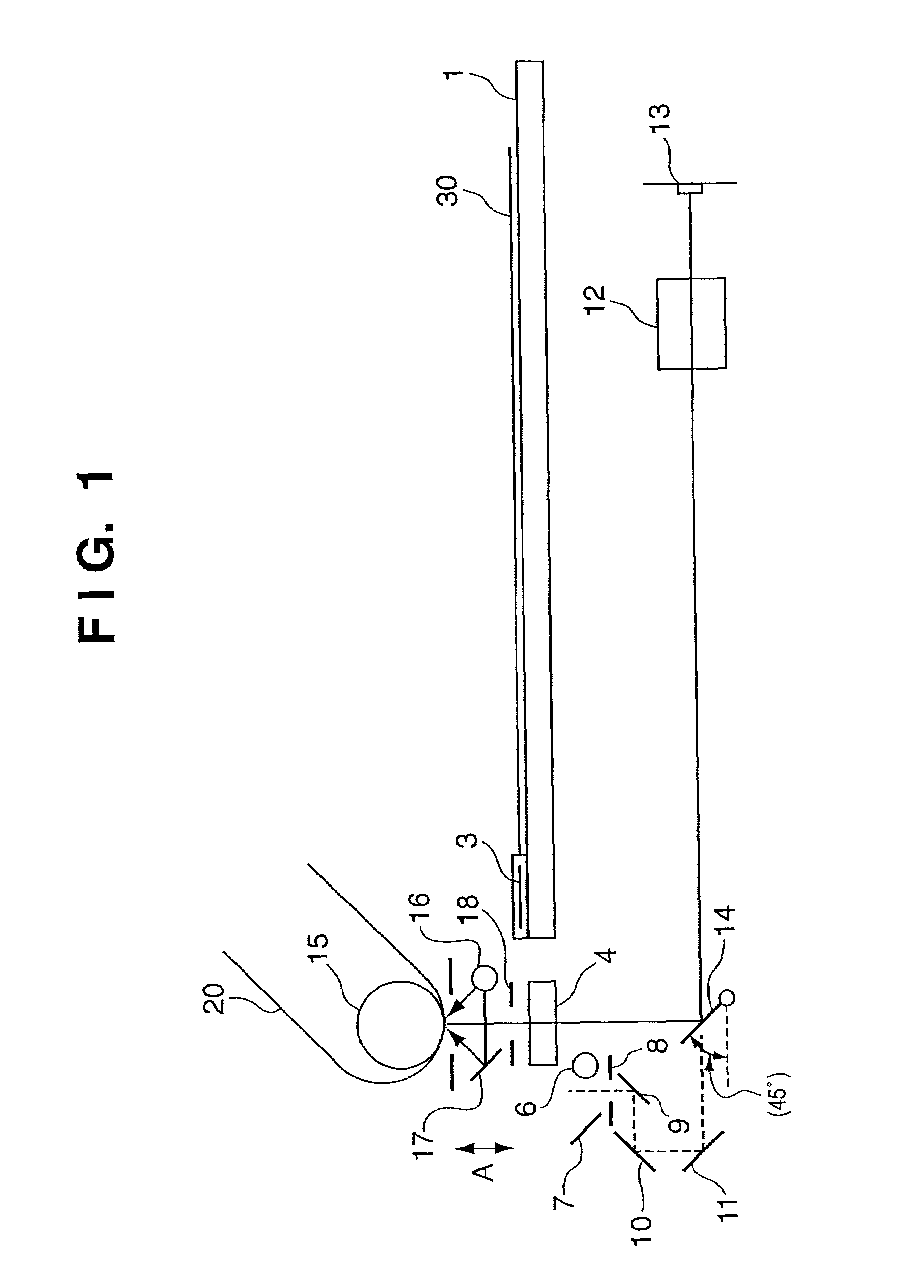
[0021]FIG. 1 is a view showing the arrangement of an image reading apparatus according to the first embodiment of the present invention. In this image reading apparatus, an original 20 conveyed by a convey roller 15 is illuminated by an illumination system comprised of an illumination light source 16 and reflecting member 17 and different from an illumination system in the reading apparatus body and comprised of an illumination light source 6 and reflecting member 7. After a light beam reflected by the original 20 passes through a slit 18 and scan flow glass member 4, it forms an image on a line sensor 13, e.g., a CCD, by an imaging lens 12 through a movable mirror 14.

[0022]A DF (Document Feeder; not shown) is formed such that the original 20 moves at a position which is about 20 mm to 50 mm above the scan flow glass member 4 with almost the same focal surface as that of an original glass plate 1.

[0023]In the illumination system in the image reading apparatus body,...

second embodiment

[Second Embodiment]

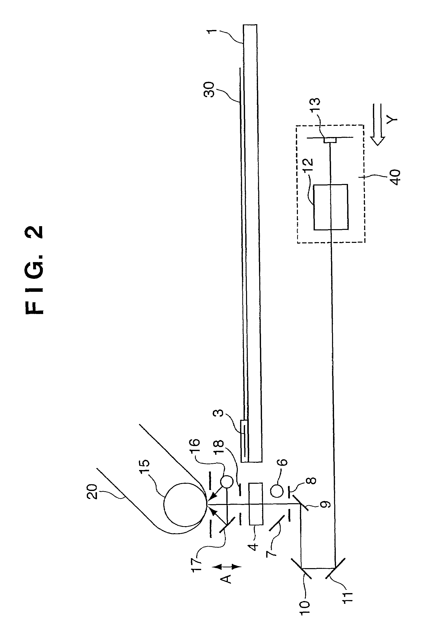
[0029]According to another embodiment, as shown in FIG. 2, an imaging lens 12 and a line sensor 13, e.g., a CCD, are integrated as a unit 40. The integrated unit 40 is moved with, e.g., a motor (not shown), in a direction Y by a distance A, so the focal surface moves upward from a scan flow glass member 4 by a distance A. An image is read while moving an original 20 in the same manner as that described above. Thus, an adverse effect of dust or a scar on the scan flow glass member 4 can be prevented.

[0030]As has been described above, according to the above embodiments, an original illumination system, different from an original illumination system that illuminates the original placed on the original glass plate, is arranged above another original glass plate arranged on substantially the same plane as that of the original glass plate and used when reading image information while moving the original, an original convey device is formed to move the original above the...


PUM


Abstract

The object of this invention is to read an image (scan flow), when an original is being moved, above a scan flow glass member, so as to prevent degradation in image caused by dust or a scar on a scan flow glass. In order to achieve this object, the original which is being moved is illuminated by an illumination system comprised of an illumination light source and reflecting member and different from an illumination system in a reading apparatus body and comprised of an illumination light source and reflecting member. After a reflected light beam passes through a slit and the scan flow glass member, it forms an image on a line sensor, e.g., a CCD, by an imaging lens through a movable mirror. As the original moves at a constant speed, it is read by the line sensor, e.g., a CCD, at a predetermined timing, thereby obtaining image information of the original. The original is located above the scan flow glass member. Even if dust or a scar of about several tens μm is present on the scan flow glass member, it goes out of focus, so it can be prevented from forming an absent point of the line sensor such as a CCD.

Description

FIELD OF THE INVENTION[0001]The present invention relates to an image reading apparatus and, more particularly, to an image reading apparatus having two different reading systems, i.e., a reading system in which an original is fixed on an original glass plate and an optical system scans it to read image information, and a reading system in which an optical system is fixed and an original is moved so image information is read from it.BACKGROUND OF THE INVENTION[0002]A conventional image reading apparatus has two different reading systems, i.e., a reading system in which an original is fixed on an original glass plate and an optical system scans it to read image information, and a reading system in which an optical system is fixed and an original is moved so image information is read from it.[0003]FIG. 3 is a view showing the arrangement of a conventional image reading apparatus, and shows a reading system in which an optical system is fixed and image information of an original 120 is...

Claims


Application Information

Patent Timeline
IPC IPC(8): H04N1/04G03B27/62H04N1/00G03B27/50G03B27/54H04N1/10H04N1/12H04N1/193
CPCH04N1/00249H04N1/00262H04N1/02409H04N1/04H04N1/0464H04N2201/0458H04N1/1013H04N1/121H04N1/193
Inventor FUKUZAWA, NOBUMASA
Owner CANON KK
Why Eureka
Try Eureka