Solid electrolytic capacitor and method for manufacturing the same

a technology of solid electrolytic capacitor and solid electrolytic capacitor, which is applied in the direction of fixed capacitor details, casings/cabinets/drawers, casings/cabinets/drawers details, etc., can solve the problems of difficult handling of bolsters (b>4/b>), difficult and labor-intensive positioning of bolsters, and reduce labor involved in manufacturing solid electrolytic capacitors. labor and the effect of resistance welding

Active Publication Date: 2006-02-07
SANYO ELECTRIC CO LTD
View PDF5 Cites 26 Cited by
  • Summary
  • Abstract
  • Description
  • Claims
  • Application Information

AI Technical Summary

Benefits of technology

[0018]1. There is a large area of contact between an anode lead (22) and a bolster member (4), because the anode lead (22) cuts into the bolster member (4). Resistance welding is therefore easier as the flow of the current is better when performing resistance welding.
[0016]Further, a method for manufacturing this solid electrolytic capacitor (1) comprises a step of lining up in the same orientation a plurality of anode bodies (20), which are provided with first wires (25), which become anode leads (22); a step of providing a second wire (40), which becomes the bolster member (4), straddling the plurality of first wires (25); a step of joining overlapping sections of the first wires (25) and the second wire (40) and letting at least a part of the first wires (25) cut into the second wire (40); a step of forming the anode lead (22) and the bolster member (4) by cutting the first wires (25) and second wire (40); and a step of placing the bolster member (4) on the terminal component portion (80), which becomes the anode-side lead frame (9), and joining the terminal component portion (80) and the bolster member (4).

Problems solved by technology

Welding is difficult if that contact area is small, as the flow of current when performing a resistance weld deteriorates.
2. Handling of the bolster member (4) is difficult, as it rolls around and gets lost easily, because its diameter and length are both 1 mm or lower and its shape is cylindrical.
Consequently, it is difficult and labor-intensive to position the bolster member (4) on the terminal component portion (80) while resistance-welding the terminal component portion (80) and the bolster member (4) together.

Method used


Image

  • Solid electrolytic capacitor and method for manufacturing the same
  • Solid electrolytic capacitor and method for manufacturing the same
  • Solid electrolytic capacitor and method for manufacturing the same

Examples


Embodiment Construction

[0033]The following is a detailed description of an embodiment of the present invention, with reference to the drawings.

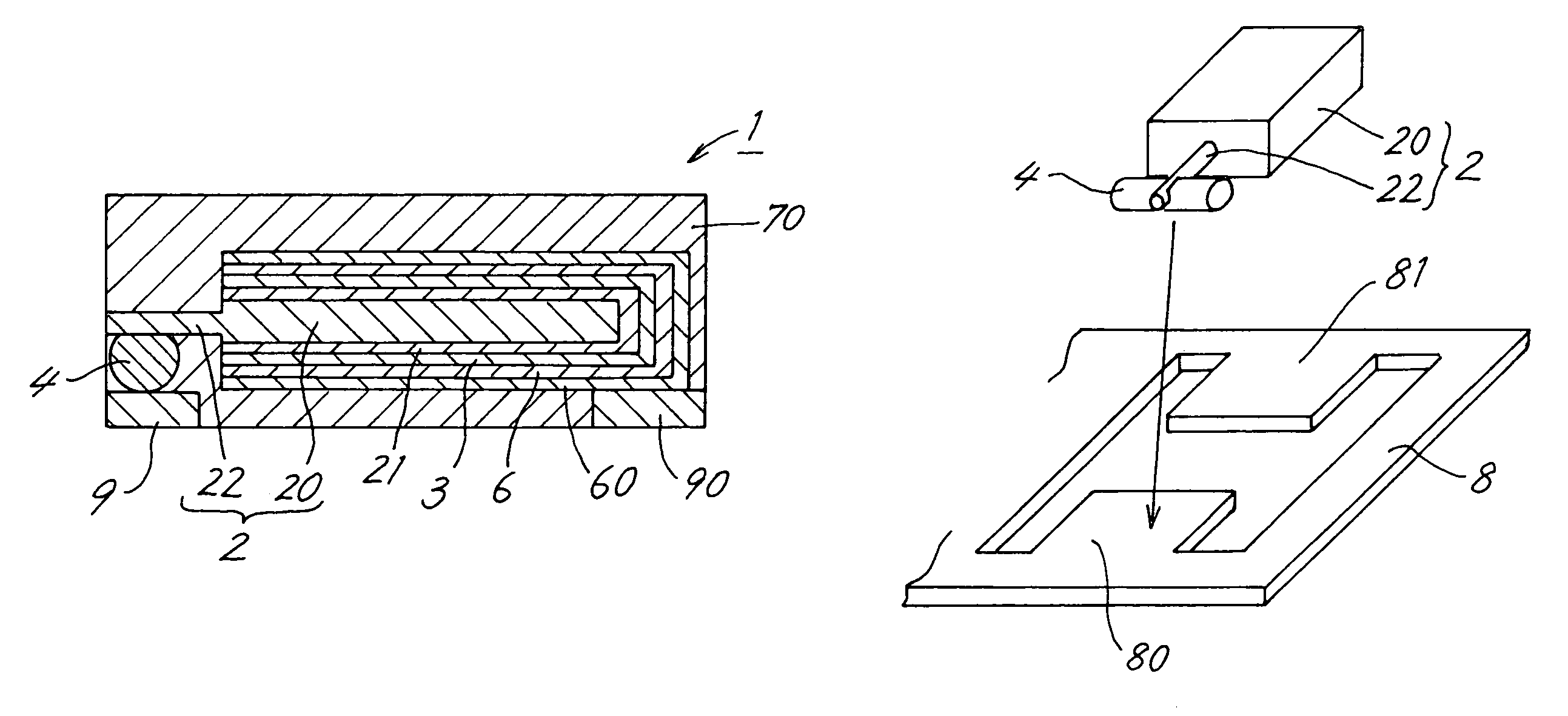
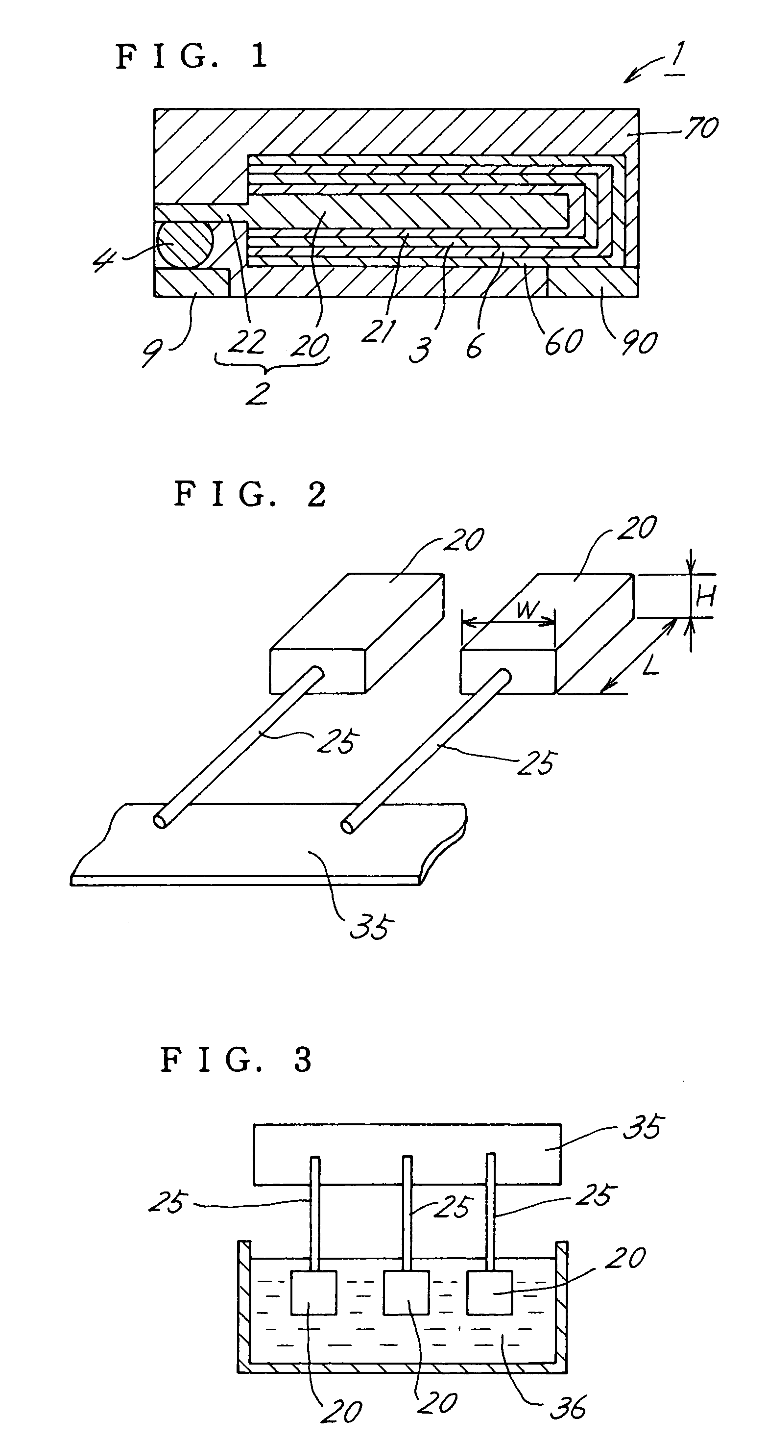
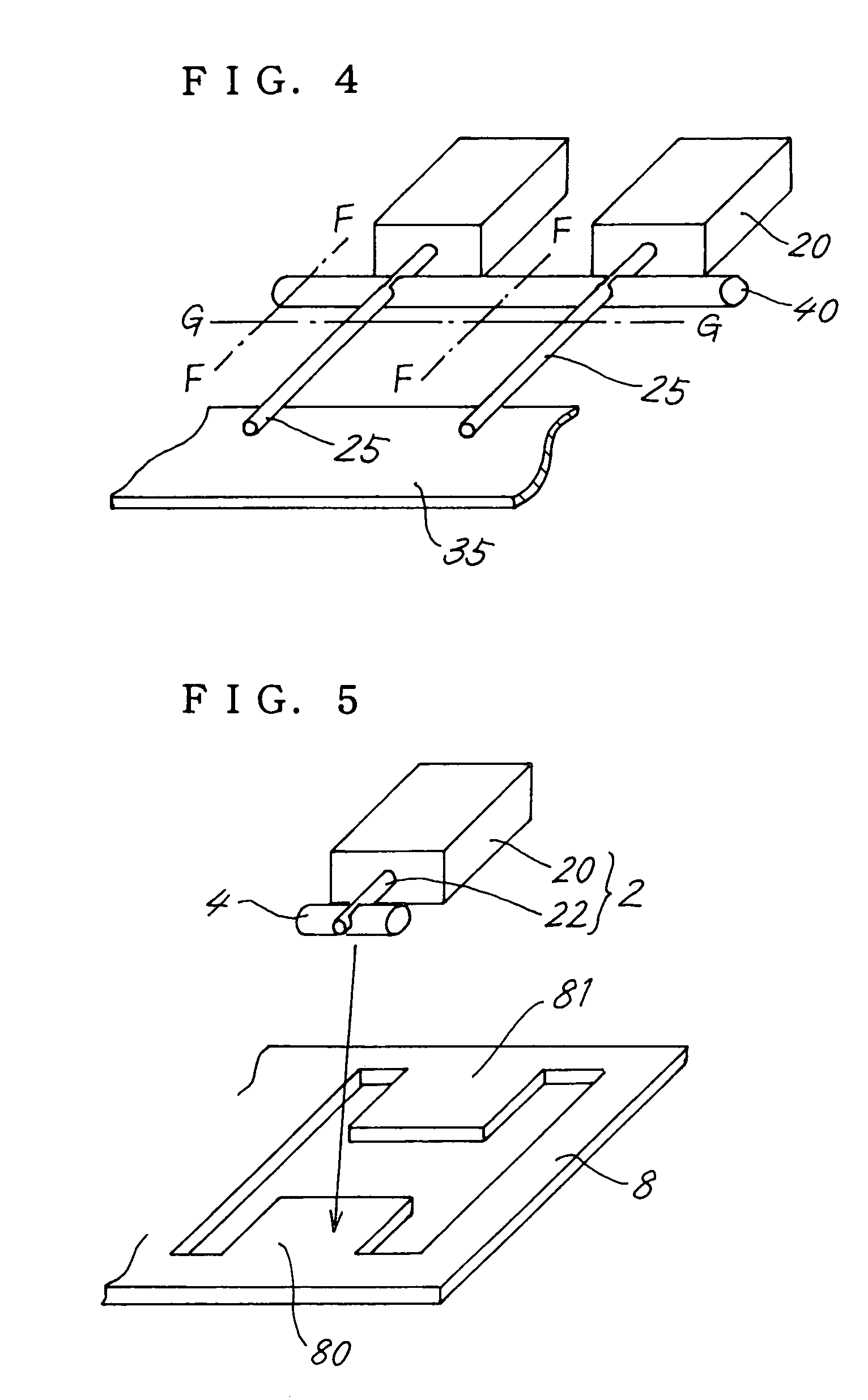
[0034]FIG. 1 is a cross-sectional view of a solid electrolytic capacitor (1). The solid electrolytic capacitor (1) is provided with a capacitor element (2) to a bottom surface of which is attached a lead frame (9), (90), the capacitor element (2) being covered by a synthetic resin housing (70), made from epoxy resin or the like. The capacitor element (2) comprises an anode lead (22) which projects from an anode body (20), and this configuration is the same as the conventional one shown in FIG. 6.

[0035]The anode lead (22) is electrically connected to the anode-side lead frame (9) via a bolster member (4), and one portion of the anode lead (22) cuts into the bolster member (4). The amount of this cut in vertical direction is at least 50% of a diameter of the anode lead (22). Specifically, the amount that the anode lead (22) cuts into the bolster member (4) is approxi...


PUM

PropertyMeasurementUnit
lengthaaaaaaaaaa
currentaaaaaaaaaa
voltageaaaaaaaaaa

Abstract

A solid electrolytic capacitor includes a capacitor element provided with an anode body from which an anode lead projects, an anode-side lead frame positioned below the anode lead, and a bolster member which is provided between the anode lead and the anode-side lead frame and electrically connects the anode lead and the anode-side lead frame. At least one portion of the anode lead cuts into the bolster member.

Description

TECHNICAL FIELD[0001]The present invention relates to a solid electrolytic capacitor and a method for manufacturing the same.BACKGROUND ART[0002]Chip-type solid electrolytic capacitors as shown in FIG. 6 are well known (see JP 2001-6978A).[0003]A solid electrolytic capacitor (1) is provided with a capacitor element (2), to a bottom surface of which is attached a lead frame (9), (90), the capacitor element (2) being covered by a housing (70) made of a synthetic resin.[0004]The capacitor element (2) is made by forming a dielectric oxide coating (21) on the surrounding surface of an anode body (20), which is a sintered valve metal member, with a cathode layer (3), a carbon layer (6), and a silver paste layer (60) formed in this order on the dielectric oxide coating (21). Here, the term “valve metal” refers to a metal which forms an extremely compact dielectric oxide coating having durability when treated by electrolytic oxidation. Al (aluminum), Ta (tantalum), Ti (titanium), and Nb (ni...

Claims


Application Information

Patent Timeline
Patent Type & Authority Patents(United States)
IPC IPC(8): H01G4/228H01G9/10H01G9/012H01G9/04H01G9/042H01G9/15
CPCH01G9/012H01G9/042Y10T29/417
Inventor FUJII, EIZOKAMIGAWA, HIDENORIKAWANO, TADAYOSHIITO, YASUHIKOYOSHIOKA, TAKASHIUMEDA, SYOUJI
Owner SANYO ELECTRIC CO LTD
Why Eureka
Try Eureka