
Method and system for ensuring that a train does not pass an improperly configured device

a technology of improper configuration and train, applied in the field of rails, can solve the problems of engineers and conductors, insufficient time, and inability to properly configure switches

Inactive Publication Date: 2006-02-07
SIEMENS MOBILITY INC
View PDF49 Cites 125 Cited by
  • Summary
  • Abstract
  • Description
  • Claims
  • Application Information

AI Technical Summary

Benefits of technology

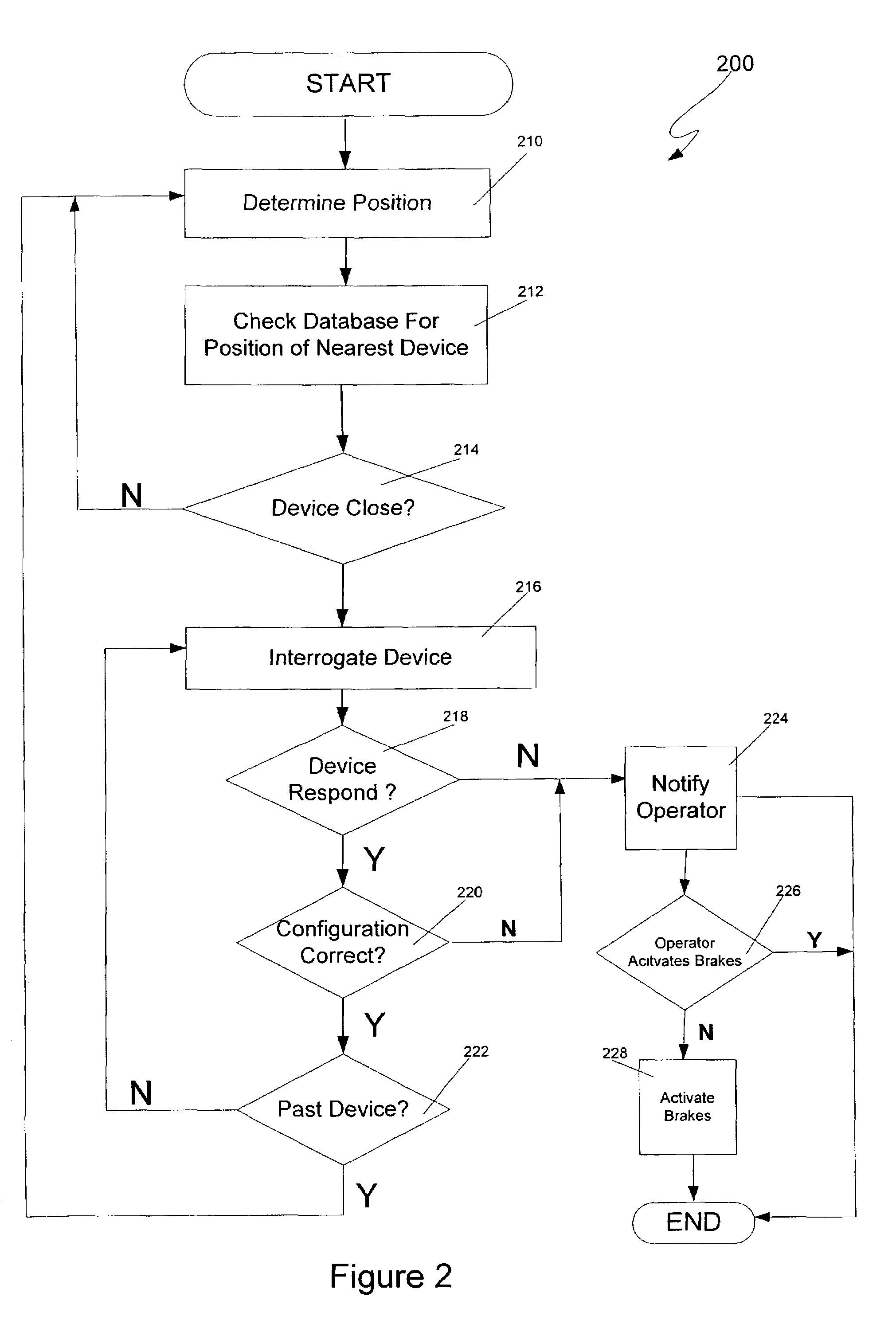
The present invention is a computerized train control system that uses GPS to determine the position of a train and a database to determine when it is approaching a switch or grade crossing gate. The system continuously interrogates the device to determine its status as the train approaches. If there is a malfunction, the system will force the engineer / conductor to acknowledge it and may stop the train if the engineer / conductor fails to do so. The technical effect of this invention is to improve safety and efficiency in train control by providing a system that can detect and respond to malfunctions in a timely manner.

Problems solved by technology

One source of accidents is an improperly set switch.
However, engineers and conductors, being human, sometimes make mistakes, including traveling too fast such that there is not sufficient time to stop the train when the signal is first visible, not activating the brakes a sufficient distance from the switch, failing to notice that the switch has been improperly set, and even forgetting to look at the switch.
The results of such mistakes can be disastrous.
Another source of accidents is a malfunctioning grade crossing gate.

Method used


Image

  • Method and system for ensuring that a train does not pass an improperly configured device
  • Method and system for ensuring that a train does not pass an improperly configured device
  • Method and system for ensuring that a train does not pass an improperly configured device

Examples


Embodiment Construction

[0013]The present invention will be discussed with reference to preferred embodiments of train control systems. Specific details, such as specific algorithms and hardware, are set forth in order to provide a thorough understanding of the present invention. The preferred embodiments discussed herein should not be understood to limit the invention. Furthermore, for ease of understanding, certain method steps are delineated as separate steps; however, these steps should not be construed as necessarily distinct nor order dependent in their performance.

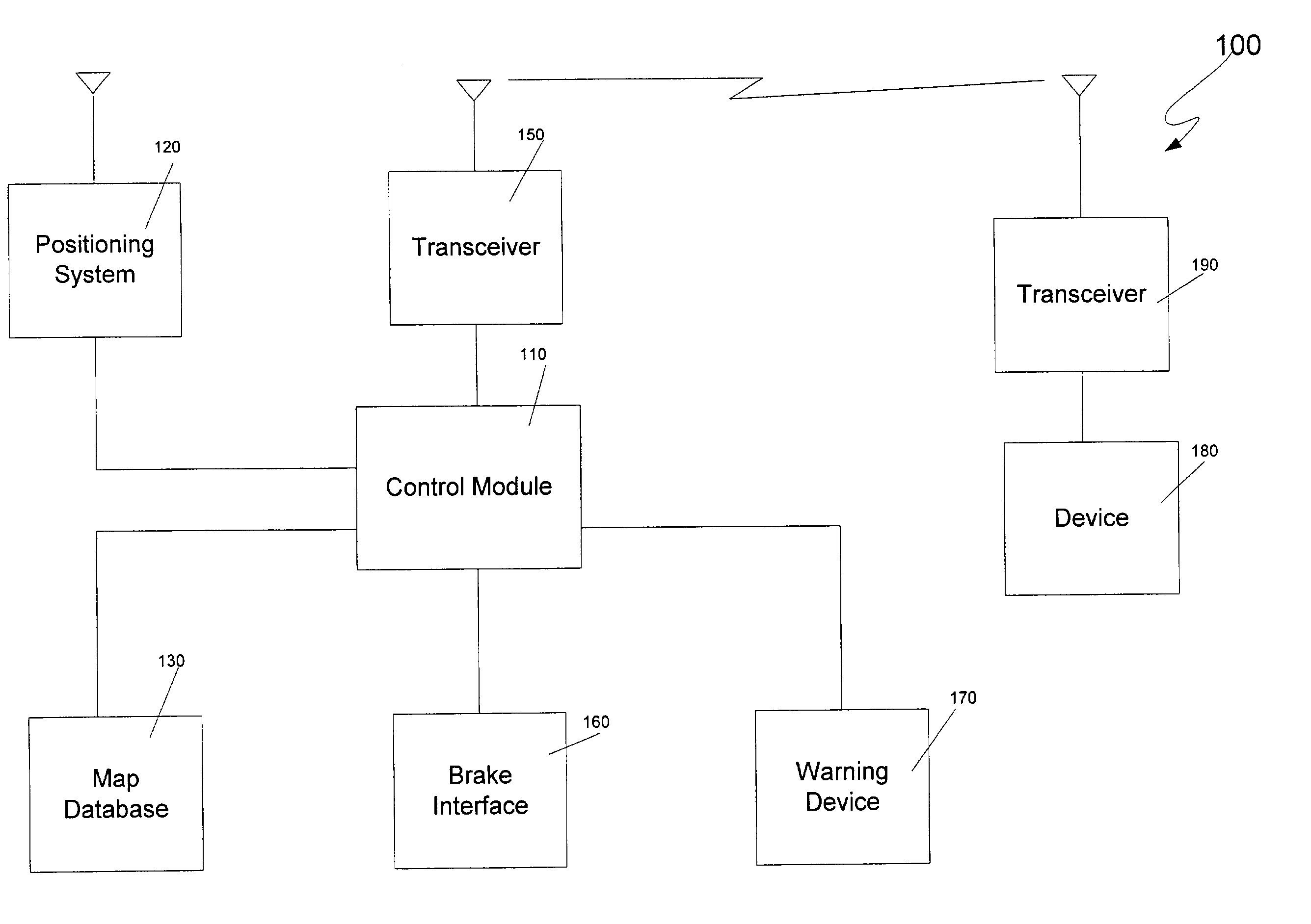
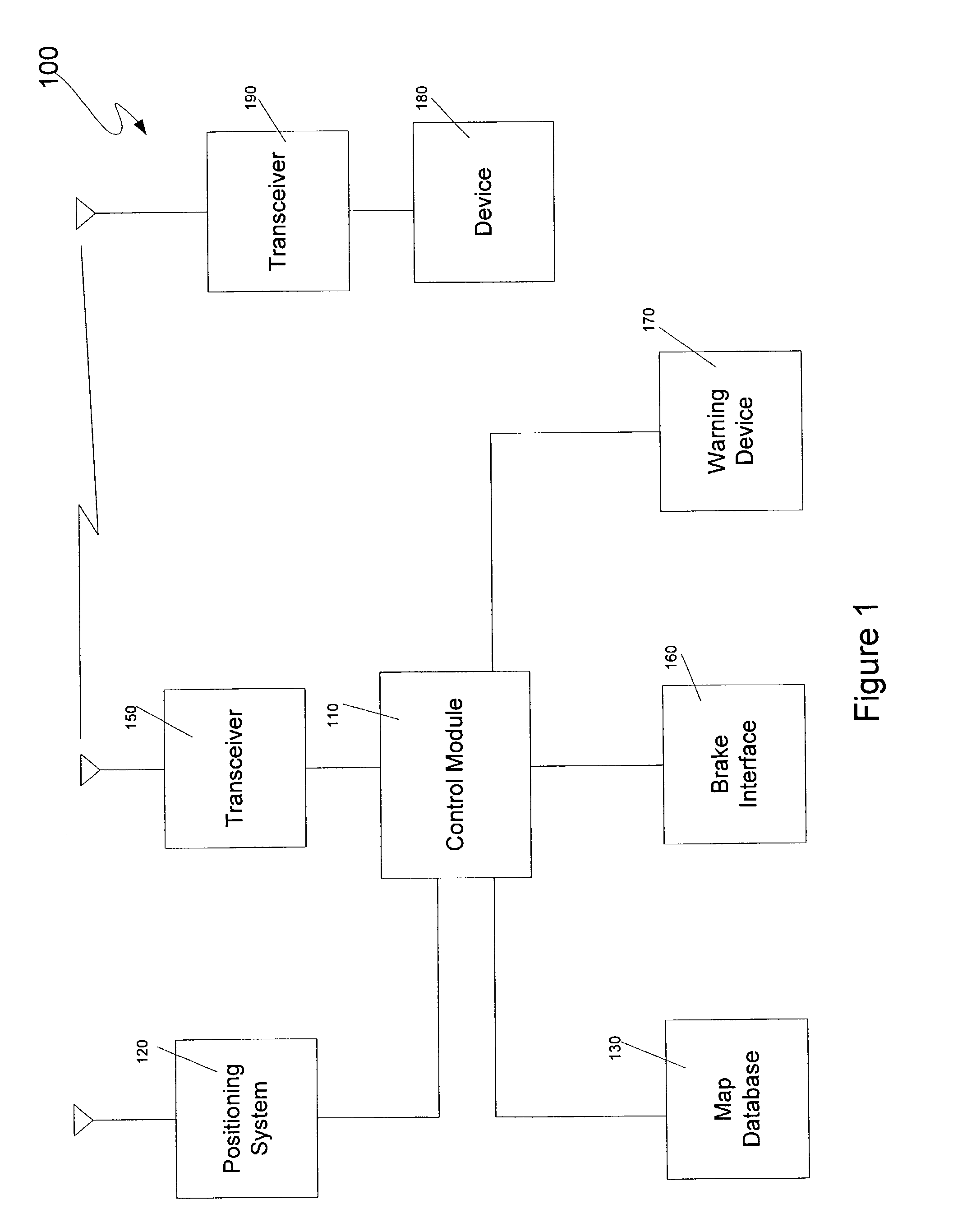
[0014]Referring now to the drawings, wherein like reference numerals designate identical or corresponding parts throughout the several views, FIG. 1 is a logical block diagram of a train control system 100 according to an embodiment of the present invention. The system 100 includes a control module 110, which typically, but not necessarily, includes a microprocessor. The control module 110 is responsible for controlling the other component...


PUM


Abstract

A train control system includes a positioning system and consults a database to determine when the train is approaching a configurable device such as a switch or grade crossing gate. The system continuously interrogates the device to determine its status as the train approaches the device, and forces an engineer / conductor to acknowledge any detected malfunction. The train is forced to come to a complete stop before proceeding past the device or may be slowed down to a speed that will allow the engineer / conductor to visually determine whether it is safe to proceed past the device if the engineer / conductor acknowledges a message warning of the malfunction and will stop the train if the engineer / conductor fails to acknowledge the warning message.

Description

BACKGROUND OF THE INVENTION[0001]1. Field of the Invention[0002]The invention relates to railroads generally, and more particularly to a method and system for ensuring that a train does not pass a device such as a grade crossing gate or a track switch when that device is not properly configured.[0003]2. Discussion of the Background[0004]Train safety has always been a concern in the railroad industry. If anything, this concern has increased in recent years. This concern has led to proposals for and development of automated, safety-enhancing systems such as Automatic Train Control (ATC), Positive Train Control (PTC), and others. While such systems vary in their implementation, one goal they all share is to avoid accidents.[0005]One source of accidents is an improperly set switch. Historically, an engineer or conductor would visually verify that a switch has been set to the correct position. However, engineers and conductors, being human, sometimes make mistakes, including traveling to...

Claims


Application Information

Patent Timeline
Patent Type & Authority Patents(United States)
IPC IPC(8): G05D13/00B61L3/00B61L3/12B61L3/22B61L29/22
CPCB61L3/004B61L3/125B61L29/22B61L3/22B61L2205/04B61L15/0092
Inventor KANE, MARK EDWARDSHOCKLEY, JAMES FRANCISHICKENLOOPER, HARRISON THOMAS
Owner SIEMENS MOBILITY INC
Learn More