
Highly scalable least connections load balancing

a load balancing and low-cost technology, applied in the field of load balancing traffic, can solve the problems of consuming a fair amount of processing time of the device that is performing load balancing, unable to ensure that the various real servers are indeed effective load balancing, and server can become a bottleneck in the network

Active Publication Date: 2006-02-07
CISCO TECH INC
View PDF16 Cites 203 Cited by
  • Summary
  • Abstract
  • Description
  • Claims
  • Application Information

AI Technical Summary

Benefits of technology

[0010]Each of the LCCBs is associated with a list of server metric / pointers that points to servers having a similar number of connections. Because the LCCBs are kept in sorted order (in terms of the number of connections in a server), finding the least loaded server is simply a matter of selecting the LCCB with the lowest connections and taking the first real server with the lowest metric (which is pointed to by the LCCB). The metric of the server is revised and the server metric / pointer is transferred to another LCCB which corresponds to the server's new number of connections. In particular, when a connection is added to the server, the remainder (which is also called a “slope”) is incremented, and when a connection is removed, the slope is decremented. When the slope equals the weight, or goes below zero, the metric is updated and the slope reset.

Problems solved by technology

As a result, the server can become a bottleneck in the network.
However, the round-robin method does not insure that the various real servers are indeed effectively load balanced.
Compared with the round-robin method, the least connections method provides for a more accurate load balancing of the servers; however, it is rather complex and consumes a fair amount of processing time of the device that is performing the load balancing.
However, one aspect of this problem is that as greater numbers of real servers are added, the load balancing process slows down, which may require replacing the load balancing device with one that processes at a faster speed.

Method used


Image

  • Highly scalable least connections load balancing
  • Highly scalable least connections load balancing
  • Highly scalable least connections load balancing

Examples


Embodiment Construction

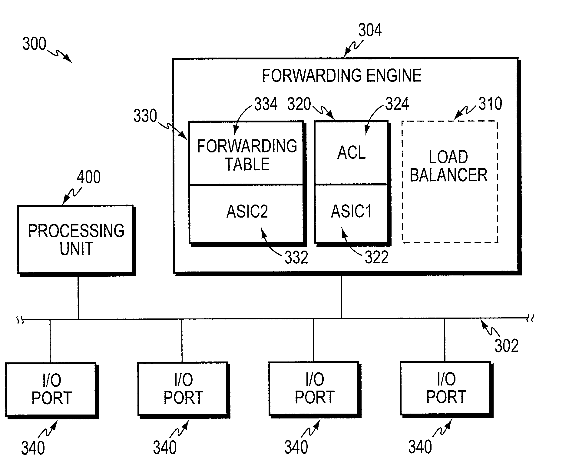
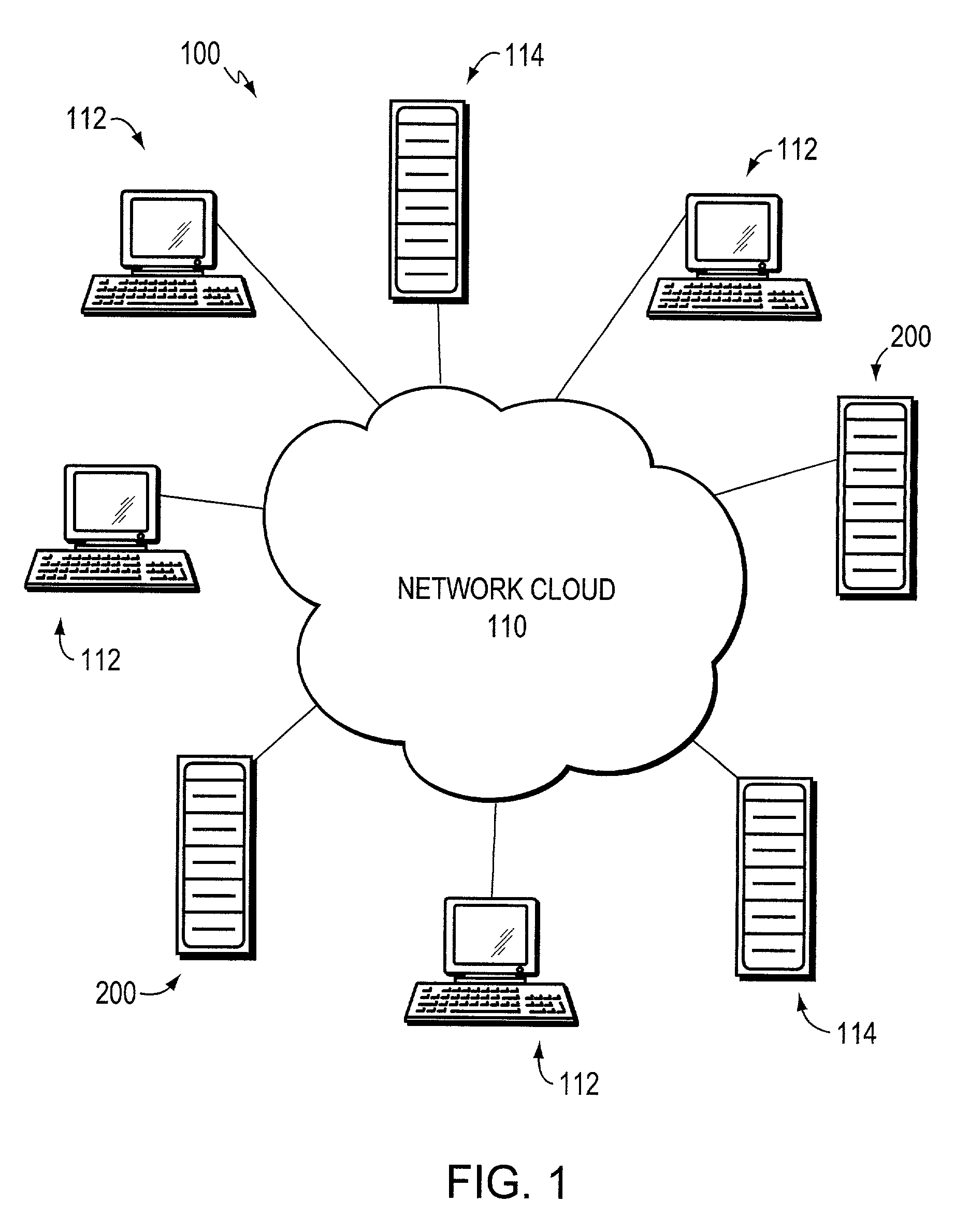
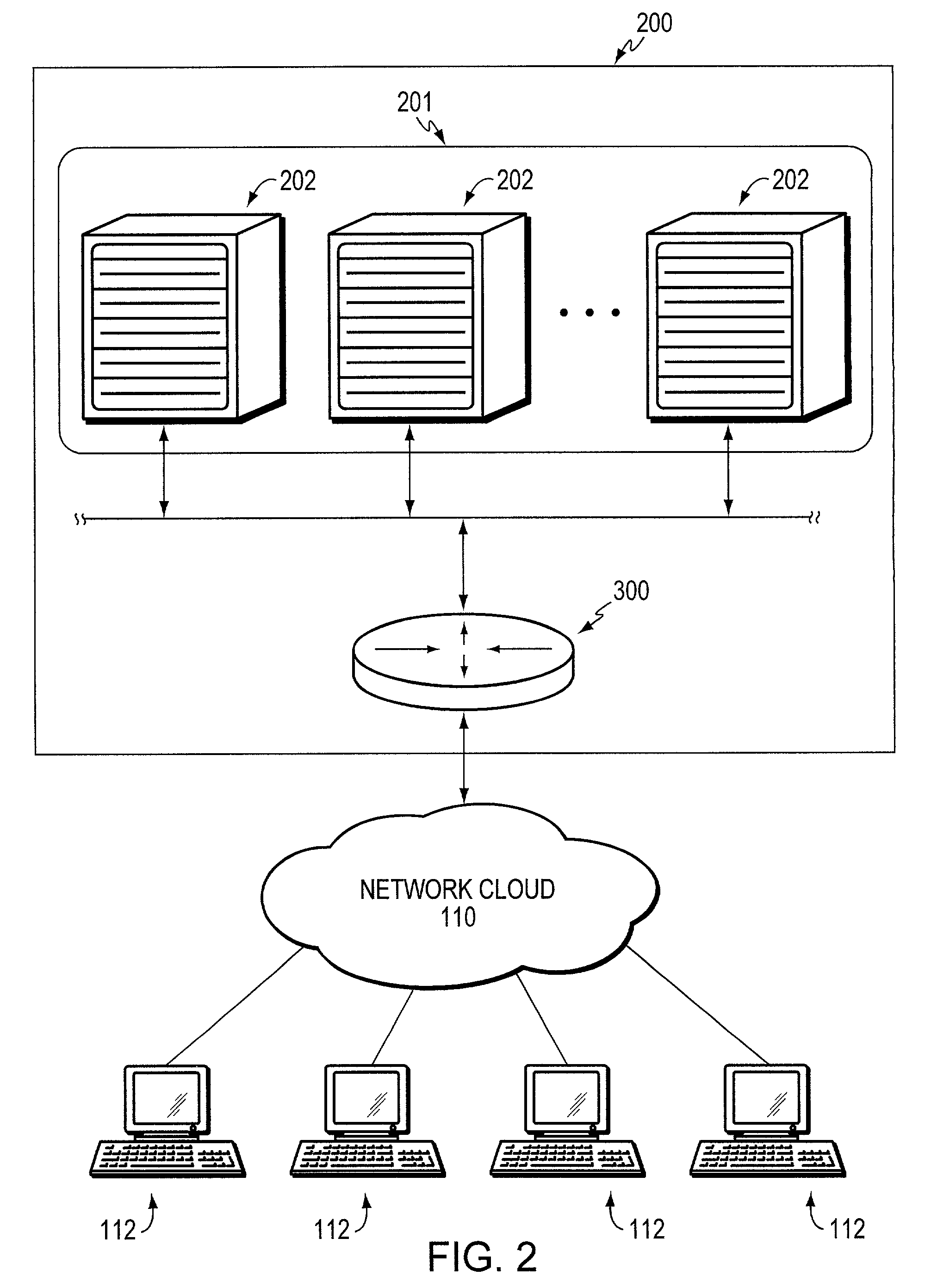
[0019]FIG. 1 shows an illustrative network 100 including a network cloud 110 which may be a combination of transmission lines, backbones, switches, routers and repeaters, dependent on the extent of the network, and allows various devices connected to the network to communicate with each other. These various devices may include simple computers such as personal computers (PCs) and workstations 112, (herein referred to as clients) that transmit or receive data, or they may be sophisticated servers 114 that store various resources. The network 100 may also include virtual servers 200, which operate in accordance with an embodiment of the present invention, to exchange data with clients 112. The network cloud 110, for instance, may be the Internet that interconnects large numbers of these simple computers, servers and virtual servers to facilitate the exchange of information. Information, in one example, flows in packets having attached headers that include, among others, source and des...


PUM


Abstract

A load balancing device according to an embodiment of the invention uses a predictor that comprises a plurality of Least Connections Control Blocks (LCCBs) that keeps track of the real servers with active connections. To speed up the search for the real server with the least number of active connections, an LCCB is kept for each metric. A metric is defined as the number of connections on a server divided by its weight (or capacity) of the server. This metric is kept as a quotient / remainder pair. The predictor sends out the real server address with the lowest metric whenever a new connection is required by the load balancing device.

Description

CROSS-REFERENCE TO RELATED APPLICATIONS[0001]The present application claims priority from U.S. Provisional Patent Application Ser. No. 60 / 236,555, which was filed on Sep. 29, 2000, by Jacob M. McGuire for a HIGHLY, SCALABLE LEAST CONNECTIONS LOAD BALANCING and is hereby incorporated by reference.BACKGROUND OF THE INVENTION[0002]1. Field of the Invention[0003]The present invention relates to load balancing traffic among a plurality of servers, and in particular, to a least connections load balancing method.[0004]2. Background Information[0005]Computer networks typically use file servers which frequently operate under a client-server paradigm. Under this model, multiple clients can make input / output (I / O) requests which are directed to a particular resource on the network. A server on the network receives and carries out the I / O requests. When the server receives multiple I / O requests, the server may choose to service them one at a time. I / O requests which are not being processed typi...

Claims


Application Information

Patent Timeline
Patent Type & Authority Patents(United States)
IPC IPC(8): G06F15/173G06F9/46
CPCG06F9/505H04L67/1008H04L69/163H04L69/164H04L67/1002H04L69/16G06F2209/5016H04L67/1001
Inventor MCGUIRE, JACOB M.
Owner CISCO TECH INC
Learn More