Cluster system

a cluster system and cluster technology, applied in the field of cluster system configuration, can solve the problems of inactive counterpart, loss of computer error information, communication impossible,

Inactive Publication Date: 2007-12-13
HITACHI LTD
View PDF30 Cites 77 Cited by
  • Summary
  • Abstract
  • Description
  • Claims
  • Application Information

AI Technical Summary

Benefits of technology

[0021] According to the present invention, the configuration of a cluster that is composed of two computers and has no storage shared between the computers for cluster control helps to prevent the both computers from behaving as master as a result of executing failover due to wrong recognition of states of a counterpart...

Problems solved by technology

However, the computers to constitute the cluster cannot determine from state monitoring alone by network communication that the communication has been impossible due to failure in the counterpart, malfunction in network processing or network equipment in an own line, or trouble in the networks themselves.
As a result, a computer in one line may incorrectly determine that the counterpart is inactive du...

Method used


Image

  • Cluster system
  • Cluster system
  • Cluster system

Examples


first embodiment

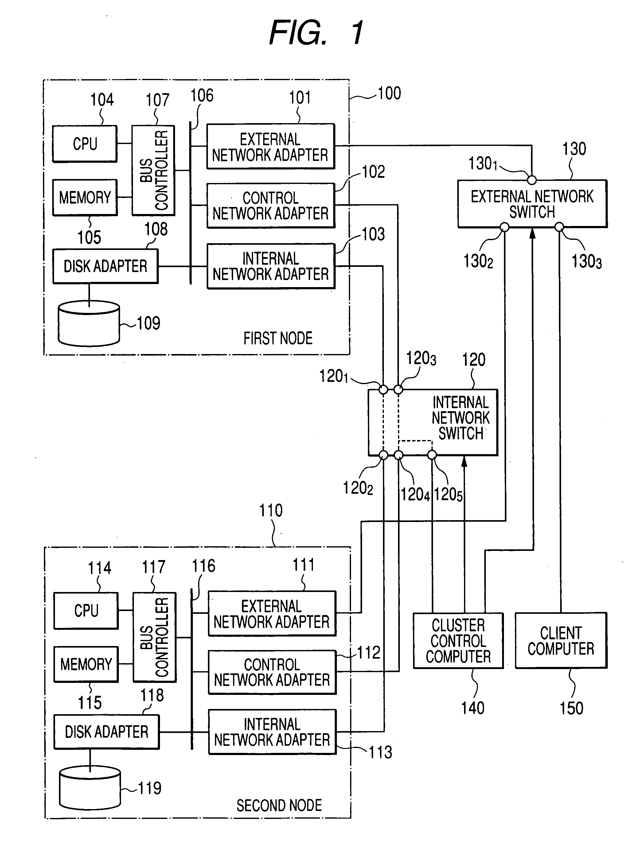
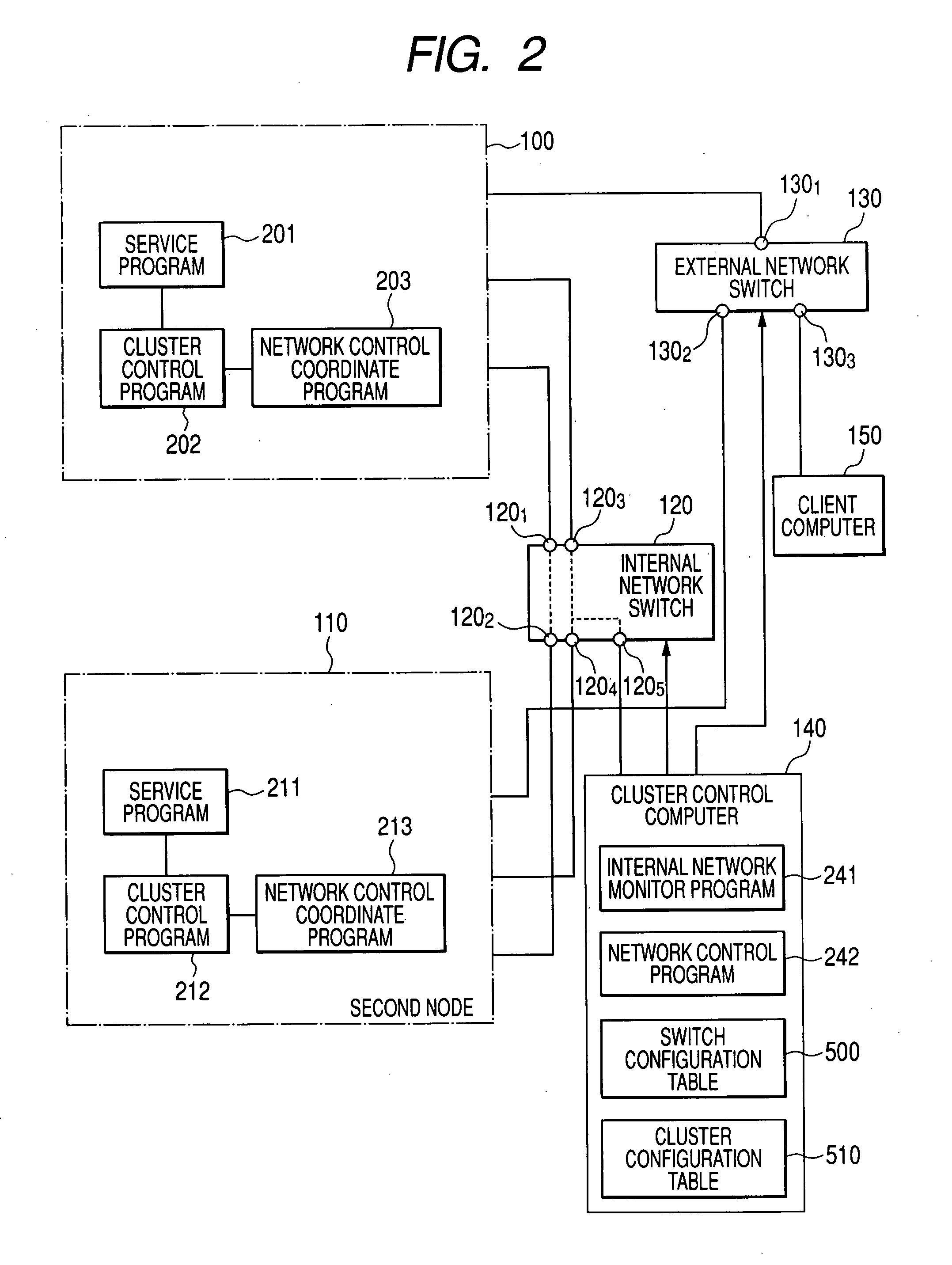
[0032]FIG. 1 is a block diagram showing the configuration of a system of a first embodiment of the present invention. A cluster in the present invention includes a computer 100 of a first node and a computer 110 of a second node that constitute the cluster, an internal network switch 120 that forms a communication network between the nodes, a client computer that accesses each of the nodes, an external network switch 130 that forms a communication network between the nodes and the client computer, and a cluster control computer 140 that receives information from each node and executes programs for controlling the enabling or disabling of ports of the network switches.

[0033] The computer 100 of the first node and the computer 110 of the second node are normal computers, and respectively include CPUs 104 and 114, memories 105 and 115, bus controllers 107 and 117 that control connection between them and buses 106 and 116, and storage devices 109 and 119 connected to the buses 106 and ...

second embodiment

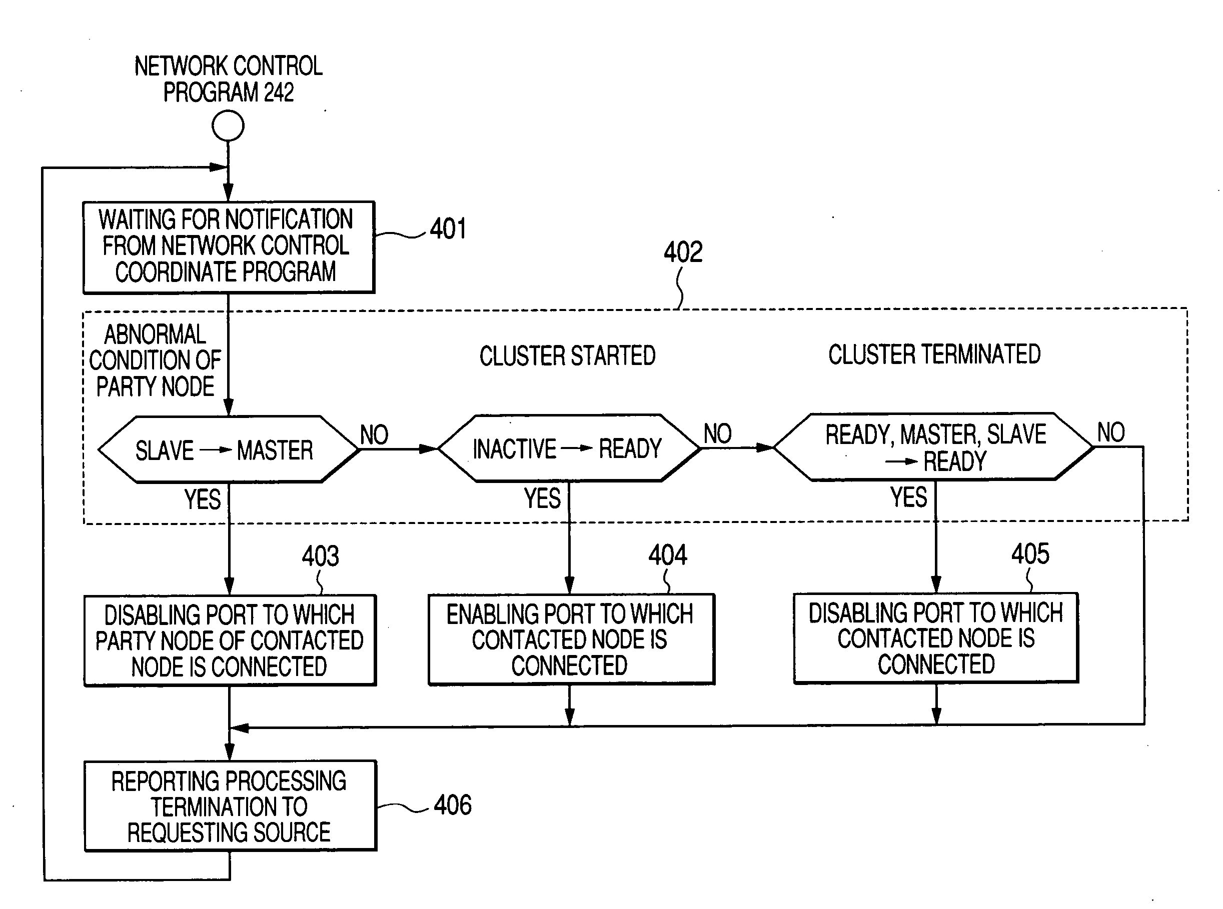
[0068] In the second embodiment, in addition to the control of the first embodiment, control described below is executed. The network control program 242 executed in the cluster control computer 140 refers to network statistics on transmission and reception of the ports of the internal network switch 120 to constitute a network for mutual monitoring of the node computers, and when communication with a computer of a party node is determined to be interrupted, notifies the cluster control programs 202 and 212 of the fact and requests failover from them. Alternatively, the network control program 242 controls the switch to disable the port connected to the computer of the party node with which communication is determined to be interrupted.

[0069] The following describes in detail the second embodiment of the present invention. In the second embodiment, the cluster control computer 140 refers to network statistics on communication states of an internal network collected by the internal ...


PUM


Abstract

In a cluster that is composed of two computer nodes and has no common storage, mutual aliveness is monitored over networks. However, this is insufficient because a party node may be wrongly determined as inactive. If failover is performed according to wrong determination, the counterpart may be restored to a normal condition after the failover, so that both the two computers may operate as master. The two nodes to constitute the cluster and other computers to communicate with the cluster are connected by switches that can disable ports to which the computers are connected. A network control program that controls the switches changes the legality of use of ports to which the nodes are connected, synchronously with node failover.

Description

CLAIM OF PRIORITY [0001] The present application claims priority from Japanese Patent Application JP 2006-130037 filed on May 9, 2006, the content of which is hereby incorporated by reference into this application. BACKGROUND OF THE INVENTION [0002] (1) Field of the Invention [0003] The present invention relates to a configuration for achieving high availability of a cluster system composed of two computers and a control means thereof. More particularly, it relates to a method for achieving high availability of a cluster system configured to have no external storage shared between two computers. [0004] (2) Description of the Related Art [0005] The concept of a cluster exists as a method for increasing availability of processing performed in a computer system. In a cluster system, identical programs are installed in plural computers, and some of the computers perform actual processing. The remaining computers, when detecting a failure in a computer that is performing processing, perf...

Claims


Application Information

Patent Timeline
IPC IPC(8): G06F15/173
CPCG06F11/2038H04L69/40H04L43/0817G06F11/2048
Inventor SEKIGUCHI, TOMOKIAMANO, KOJIOHIRA, TAKAHIRO
Owner HITACHI LTD
Why Eureka
Try Eureka