Structures which can be dismantled and folded, consisting of interconnecting tubular elements

a tubular element and folding technology, applied in the field of folding structures, can solve the problems of long complex and onerous setting-up operations, and the plurality of articulated elements, and achieve the effects of ensuring the stability of the joined structure, and reducing the number of assembly and disassembly times

Inactive Publication Date: 2006-02-14
CAZZOLARO SERGIO
View PDF29 Cites 12 Cited by
  • Summary
  • Abstract
  • Description
  • Claims
  • Application Information

AI Technical Summary

Benefits of technology

[0007]It is one object of this invention to provide a simple and rapid method of joining two or more structures of the type comprising pairs of extended tubular shear-connected elements, whose extremity is hinged in universal joints and in which the universal joints are defined integral with equal and parallel larger faces and are preferably substantially parallelepiped in form and present four hinging seats set in one of the larger faces near a side face.
[0009]It is yet another object of this invention to provide a device that allows the coupling of the aforesaid structures.
[0014]It has been found, however, that to get sufficient stability, in most cases it is sufficient to apply the C-springs only on the external faces of the universal joints that are on the external surface of the structure. The application of the C-springs to only the external faces of the joints enormously simplifies the operation of assembly and dismantling of the coupled structures.
[0015]To further guarantee the stability of the joined structure, the faces of the matching joints can form one or more suitable perforations for the housing pivots that prevent any movement of the joints on the contact pivot.

Problems solved by technology

The structure described in this patent is complex, provides for a plurality of articulated elements and therefore requires long assembly and dismantling times.
This system also presupposes complex and onerous setting-up operations, as well as relatively long dismantling and assembly times.

Method used


Image

  • Structures which can be dismantled and folded, consisting of interconnecting tubular elements
  • Structures which can be dismantled and folded, consisting of interconnecting tubular elements
  • Structures which can be dismantled and folded, consisting of interconnecting tubular elements

Examples


Embodiment Construction

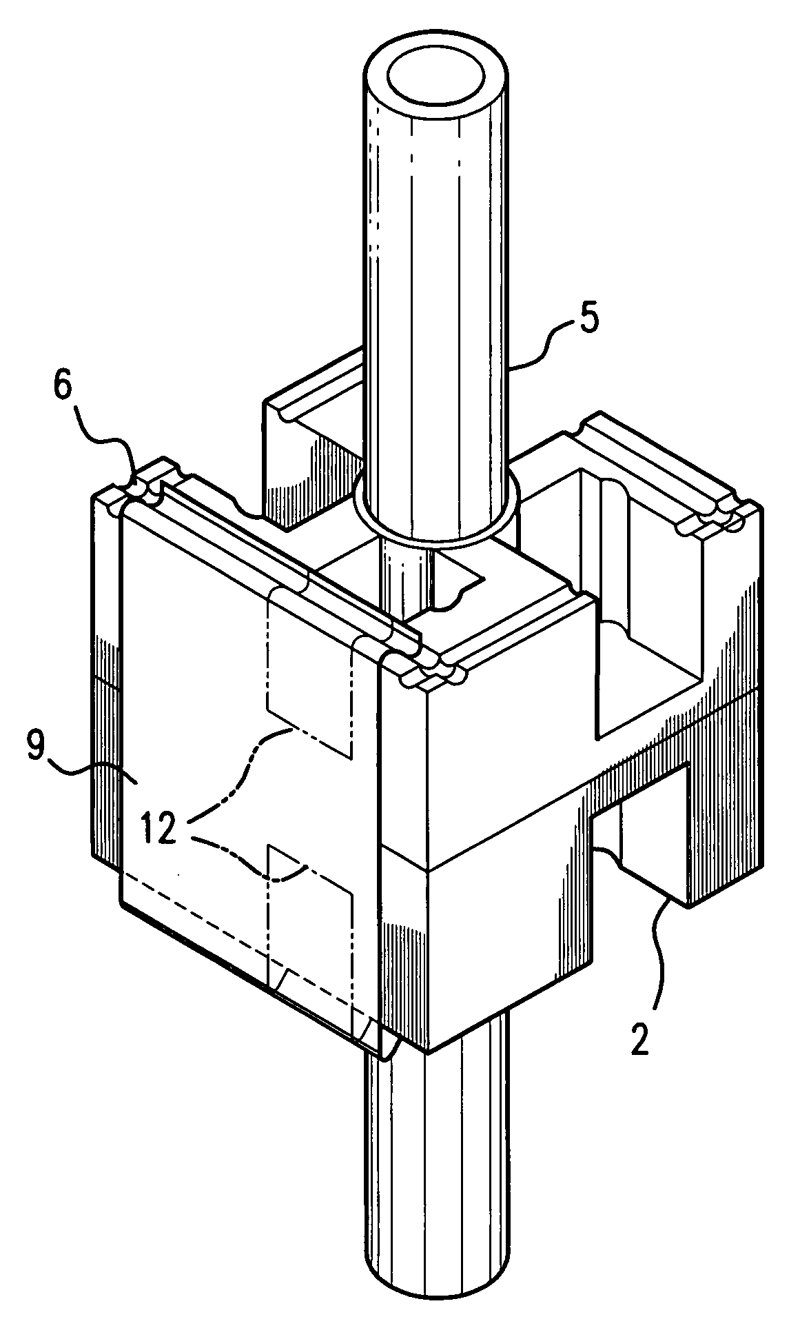
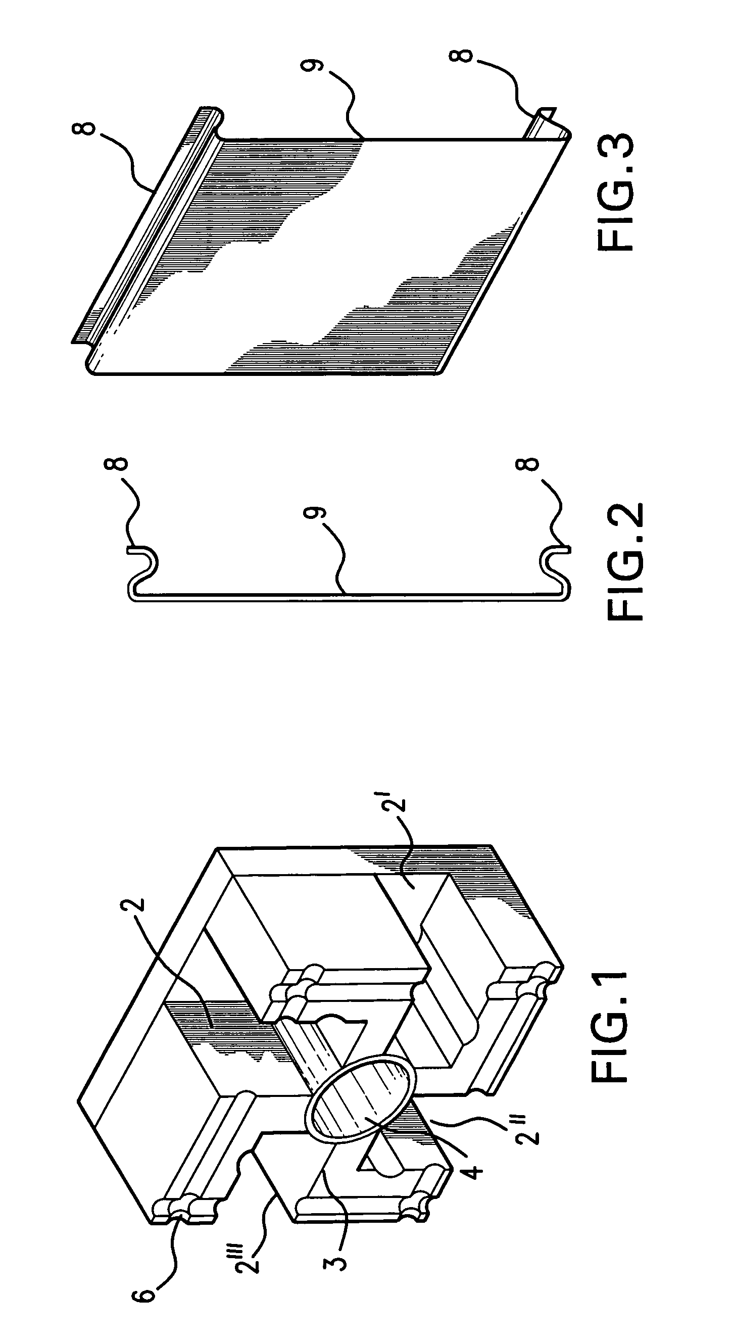
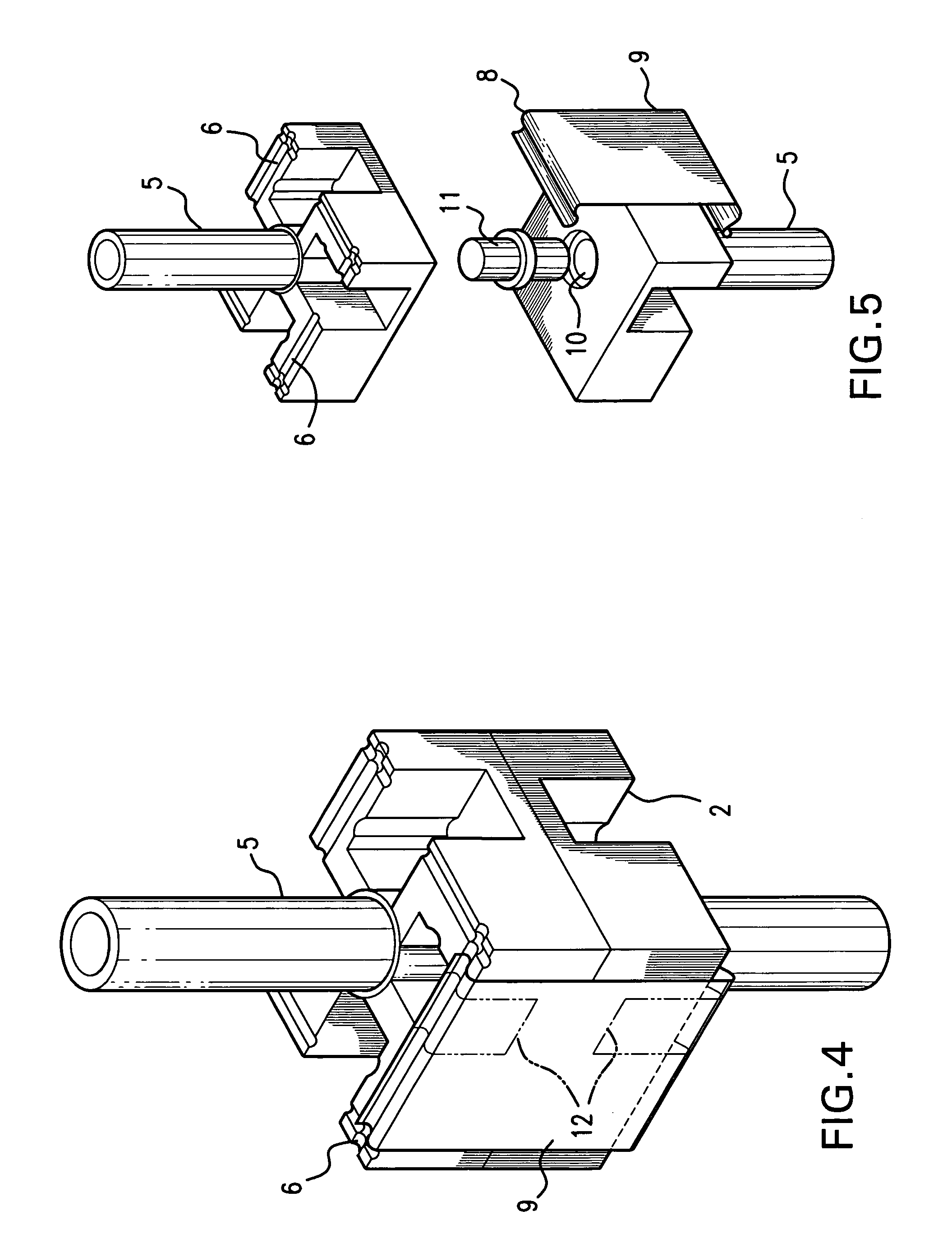
[0023]With reference to FIGS. 1 to 4, the universal joint 1 forms four seats 2, 2′, 2″ and 2′″ on one of its larger faces in correspondence with each side face, that can accept hinged extended tubular elements, not shown in the figure. On larger face 3 of the universal joint that forms the four seats (2, 2′, 2″ and 2′″) there is an opening 4 to fix the extremity of a tubular extended element 5 (shown in FIG. 4), within which another tubular element slides, not shown in the figure, and connected with a corresponding universal joint. The edges of the face of the universal joint form grooves 6 which constitute seats to accept one of the extremities 8 (shown in FIGS. 2 and 3) of a spring 9 as shown in FIG. 4. In one embodiment of the invention, as shown in FIG. 4, the spring 9 can include two cut-outs 12 (shown in phantom) that correspond to the seats (2, 2′, 2″ and / or 2′″).

[0024]The insertion of the two extremities 8 of the spring 9 into the grooves on the nonmatching faces of two join...


PUM


Abstract

Composite structures obtained by joining two or more structures of the type which presents pairs of joined tubular elements, whose extremity is hinged in universal joints and in which the universal joints are substantially parallelepiped in form and present four seats of hinging corresponding to the sides faces, in which the universal joints present grooves along the sides of the face, in which are scheduled the seats to hinge the extended elements, in proximity of the edges and parallel to the same edges, that cooperate with C-sectioned fixing elements to hold united two matched universal joints belonging to two structures from join.

Description

BACKGROUND OF THE INVENTION[0001]This invention relates to folding structures consisting of interconnected extended tubular elements. More particularly, this invention relates to portable folding structures which can be extended horizontally or vertically, that can be used for product display or as supports for raised loads, such as for instance platforms, walkway bases, technical pavements, rostrums, stands, boxes. These structures comprise a plurality of interconnected parallelepiped cells in which the sides faces of the parallelepiped are defined by a pair of tubular elements interconnected by a scissors-connector. In these structures, each extremity of the extended tubular elements which constitute the pair of scissors-connected elements, is inserted by rotation into a seat in an articulated universal joint, also parallelepiped in form. The universal joint presents, on one of the larger faces, a hinging seat corresponding to each side face, and can therefore accept up to four ex...

Claims


Application Information

Patent Timeline
Patent Type & Authority Patents(United States)
IPC IPC(8): E04C3/02E04C3/28
CPCE04C3/005E04C3/28E04H15/44G09F15/0068E04C2003/0491Y10T24/45005Y10T403/7176Y10T403/551Y10T403/50Y10T24/44778Y10T403/4354Y10T403/55Y10T403/66
Inventor CAZZOLARO, SERGIO
Owner CAZZOLARO SERGIO
Why Eureka
Try Eureka