Stand

a technology for supporting devices and stands, applied in the field of stands, can solve the problems of high probability of inappropriate adjustment of monitors or displays at one setting for one individual, high cost and wear of gas springs, and large space occupation of gas springs, so as to increase the importance of comfort for the operator

Inactive Publication Date: 2006-02-14
ERGOTRON
View PDF108 Cites 139 Cited by
  • Summary
  • Abstract
  • Description
  • Claims
  • Application Information

AI Technical Summary

Benefits of technology

[0033]It has been found that a machine in accordance with the present invention provides extremely smooth motion between a first component and a second component that slidingly engage one another. In some applications, one or more friction pads may be provided to provide a “pause” at a particular position and to provide increased stability at a particular position.

Problems solved by technology

Given the differences in people's size and differences in their preferences, a monitor or display adjusted at one setting for one individual is highly likely to be inappropriate for another individual.
An operator may choose to use the monitor as left by the previous user despite the discomfort, annoyance and inconvenience experienced by a user who uses settings optimized for another individual, which may even result in injury after prolonged use.
However, the gas springs are costly and wear out over time.
In addition, the gas springs require a significant amount of space, for instance arm length, which can be at a premium in certain applications, such as in hospitals.

Method used


Image

  • Stand
  • Stand
  • Stand

Examples


Embodiment Construction

[0061]The following detailed description should be read with reference to the drawings, in which like elements in different drawings are numbered identically. The drawings, which are not necessarily to scale, depict selected embodiments and are not intended to limit the scope of the invention. Examples of constructions, materials, dimensions, and manufacturing processes are provided for selected elements. All other elements employ that which is known to those of skill in the field of the invention. Those skilled in the art will recognize that many of the examples provided have suitable alternatives that can be utilized.

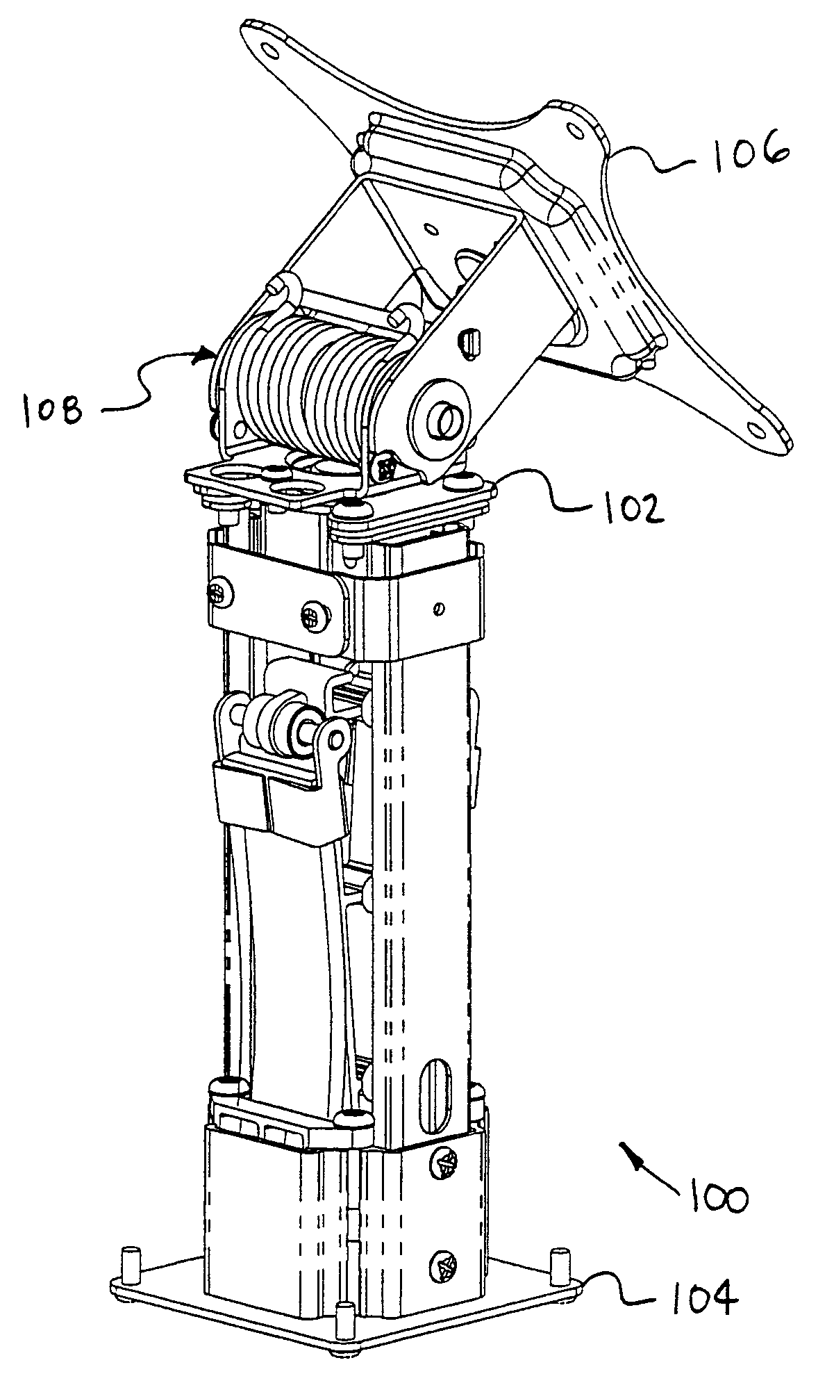
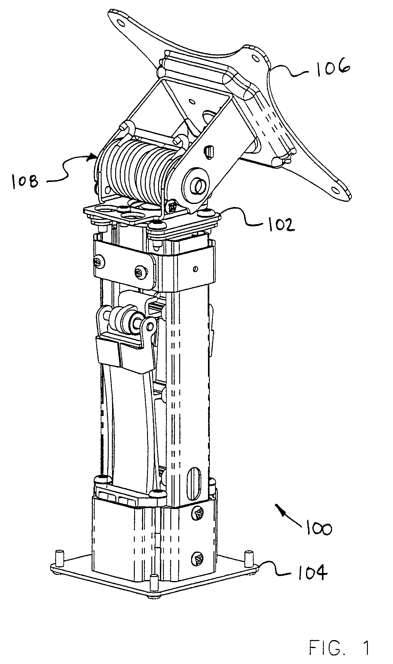
[0062]FIG. 1 is a perspective view of a stand 100 in accordance with an exemplary embodiment of the present invention. Stand 100 of FIG. 1, comprises a head 102 that is slidingly couple to a base 104. A mounting bracket 106 is coupled to head 102 by a pivot mechanism 108 in the embodiment of FIG. 1. A device such as, for example, an electronic display may be fixed to ...


PUM


Abstract

Methods and apparatus for providing an adjustable balancing force are provided. This mechanism can be used as a lifting force, a counter balancing mechanism or as a horizontal or other force mechanism. A stand in accordance with an exemplary embodiment of the present invention comprises a first component that is slidingly coupled to a second component. A spring mechanism provides a balancing force between the first component and the second component. In some advantageous embodiments of the present invention, the magnitude of the balancing force is substantially equal to a first load. In some advantageous embodiments, a friction force is provided for resisting relative movement between the first component and the second component.

Description

RELATED APPLICATIONS[0001]The present Application claims the benefit of U.S. Provisional Patent Application, Ser. No. 60 / 394,807, filed Aug. 21, 2002.[0002]The present Application claims the benefit of U.S. Provisional Patent Application, Ser. No. 60 / 434,333, filed Dec. 17, 2002.[0003]The present Application claims the benefit of U.S. Provisional Patent Application, Ser. No. 60 / 439,221, filed Jan. 10, 2003.[0004]The present Application claims the benefit of U.S. Provisional Patent Application, Ser. No. 60 / 441,143, filed Jan. 17, 2003.[0005]The present Application claims the benefit of U.S. Provisional Patent Application, Ser. No. 60 / 471,869, filed May 20, 2003.[0006]The present Application claims the benefit of a U.S. Provisional Patent Application No. 60 / 492,015 filed on Aug. 1, 2003.[0007]The entire disclosure of the above-mentioned patent applications is hereby incorporated by reference herein.FIELD OF THE INVENTION[0008]The present invention relates generally to an apparatus for...

Claims


Application Information

Patent Timeline
Patent Type & Authority Patents(United States)
IPC IPC(8): A47F5/00F16M11/04F16M11/10F16M11/24
CPCF16M11/04F16M11/10F16M11/105F16M11/2064F16M11/2092F16M11/30F16M11/24Y10S248/919F16M2200/044F16M2200/048F16M2200/063
Inventor SWEERE, HARRY C.ERGUN, MUSTAFA A.LINDBLAD, SHAUN C.OVERN, H. KARL
Owner ERGOTRON
Why Eureka
Try Eureka