
Hay bale stacker

a technology of hay bale and stacker, which is applied in the field of systems and methods, can solve the problems of cumbersome and time-consuming process for loading and unloading bales, cumbersome procedures and/or apparatuses, and/or time-consuming, and achieves the effect of increasing or decreasing the acceleration rate of the power slider mechanism and simplifying the operation of the apparatus

Inactive Publication Date: 2006-02-14
MORRIS EQUIP LTD
View PDF27 Cites 28 Cited by
  • Summary
  • Abstract
  • Description
  • Claims
  • Application Information

AI Technical Summary

Benefits of technology

[0015]Implementation of the present invention embraces a powered apparatus that slides the bales rearwardly from the loading mechanism to a rearward position on the accumulating platform, thereby eliminating the need for a steeply inclined accumulating platform to cause the bales to slide rearwardly due to gravity. Implementation of the present invention further embraces an integration of the apparatus with a computer device to selectively operate the apparatus and to simplify such operation.
[0017]In one implementation a chain tensioner is used to keep the chain taut, thereby preventing a substantial loss of chain length as the loading mechanism is lowered from an up position to a down or pick-up position. A pivotal arm with a sprocket attached to the end of the arm is used to push the chain away from two stationary sprockets on the bottom side of an accumulating platform. The pivotal arm is powered to keep a constant pressure on the chain.
[0019]The use of the computer program simplifies the operation of the apparatus by allowing the apparatus to be controlled by the use of four switches instead of seven, which is typically needed for an apparatus having seven different powered mechanisms. The computer program determines the actions that need to occur so the operator does not have to continually toggle switches in order to cause apparatus functions to occur. The computer program also enables the continuation of an action once that action is initiated by the operator.
[0020]Further implementation of the present invention allows for the ability to control the speed of the power slider mechanism as it moves the bales from the front of the loading platform to the most rearward position on the bale accumulation platform. The power slider mechanism begins slowly and picks up speed as the row of bales is pushed to the rear of the apparatus. This is enabled by writing the program so that the computer pulses the current traveling to the flow control valve. The faster the pulse to the flow control valve, the greater the flow to the orbit motor, which drives the bales. The computer program enables the computer to speed up the pulses as the position of the chain moves rearward from the first stop position. This automatically speeds up the power slider mechanism as the bales are pushed from the front to the rear of the apparatus. The rate of acceleration may be modified by a dial that is read by the computer device. The computer program may provide the necessary adjustments so that the computer device increases or decreases the rate of acceleration of the power slider mechanism by respectively sending out pulses that are faster or slower depending on where the dial is set.

Problems solved by technology

This process for loading and unloading bales has proven to be cumbersome and time-consuming, and involves two operations.
The apparatus provides substantial savings over conventional methods for loading bales, but may be somewhat difficult to operate and requires the dedication of a flatbed truck for the single purpose of loading and stacking bales.
Thus, while a variety of traditional procedures and / or apparatuses exist for loading, unloading, and otherwise handling bales, the procedures and / or apparatuses have typically proven to be cumbersome, difficult to utilize, and / or time-consuming.

Method used


Image

  • Hay bale stacker
  • Hay bale stacker
  • Hay bale stacker

Examples


Embodiment Construction

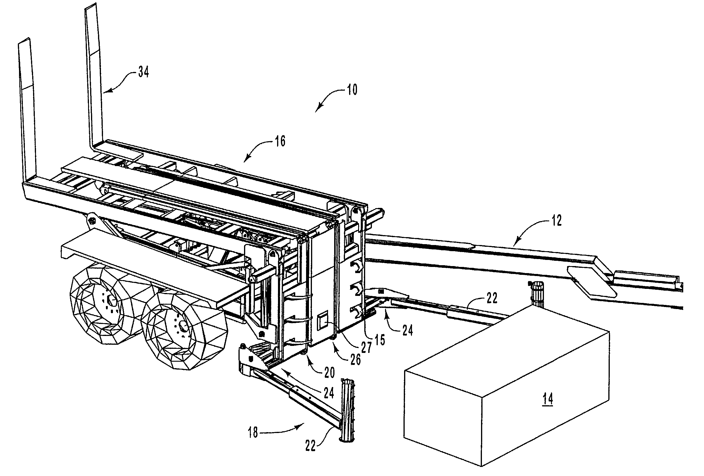
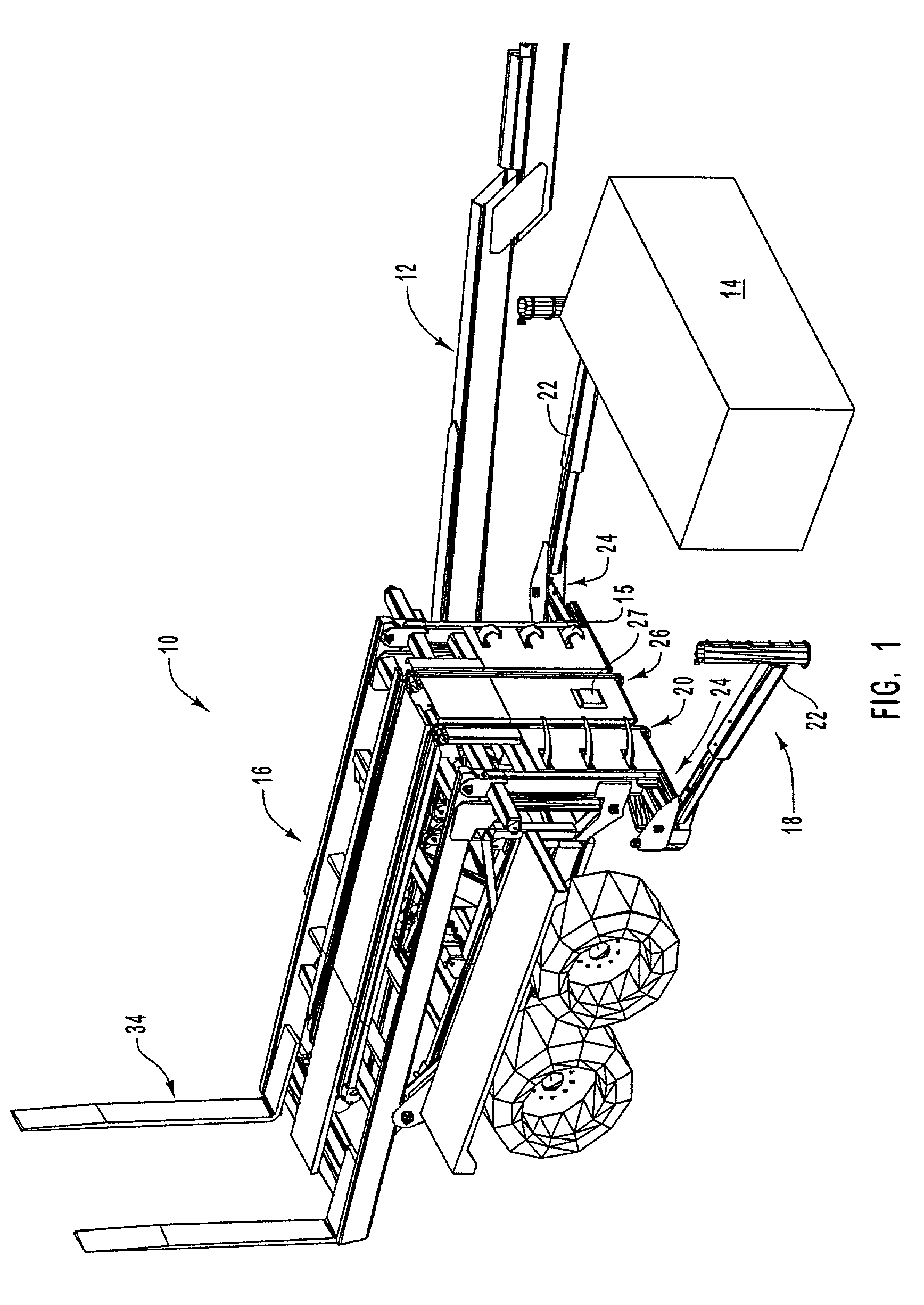
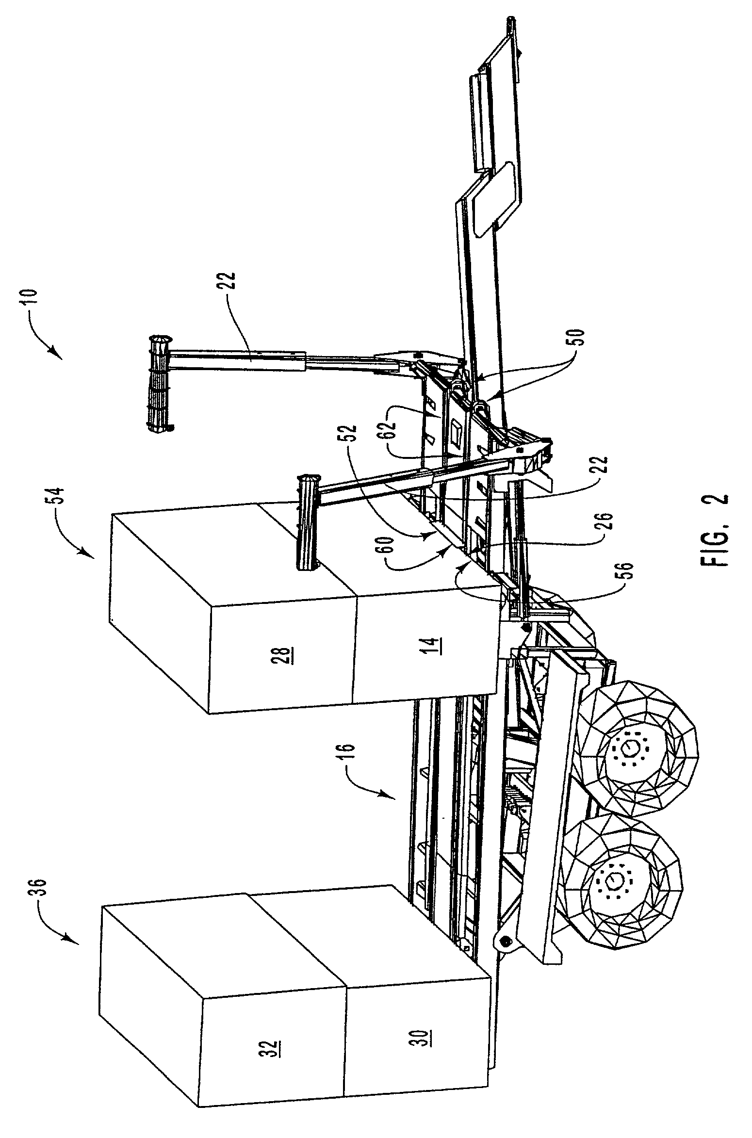
[0034]The present invention relates to systems and methods for loading, stacking, and / or handling large bales of hay. In particular, the present invention relates to a loading and stacking apparatus that incorporates a bale moving mechanism to rearwardly move a hay bale off a loading mechanism and onto a bale accumulating platform.

[0035]Embodiments of the present invention take place in association with a powered apparatus that may be used to rearwardly slide a load, such as a hay bale, feed bale, or other load, from a loading mechanism to a rearward position on an accumulating platform. As such, the need for a steeply inclined accumulating platform to cause the load to slide rearwardly is prevented. Embodiments of the present invention further embrace the utilization of a computer device, such as a logic controller or another computer device to control the apparatus in order to simplify the operation thereof.

[0036]In the disclosure and in the claims, the term “bale” shall refer to ...


PUM


Abstract

Systems, methods and apparatuses for loading, unloading, and handling bales. A powered apparatus is configured to load bales, slide the bales from a loading mechanism to a rearward position on a platform, and unload the bales from the apparatus comprises a variety of mechanisms and control systems. Such mechanisms include a bale accumulating platform, a bale loading mechanism to pick up and deposit bales on the accumulating platform, a bale sliding mechanism, and a push-off or sliding mechanism to unload bales from the apparatus. The apparatus may be positioned in a variety of configurations and a chain tensioner mechanism is used to keep chains taut. The apparatus further comprises a control system that includes a computer device or controller, sensors and switches. The sensors and switches are configured to selectively provide input to the computer device or may be used independent of the computer device to control one or more mechanisms of the apparatus.

Description

RELATED APPLICATIONS[0001]This application claims priority to U.S. Provisional Patent Application Ser. No. 60 / 260,126, filed Jan. 5, 2001, entitled “HAY BALE STACKER.”BACKGROUND OF THE INVENTION[0002]1. Field of the Invention[0003]The present invention relates to systems and methods for loading, stacking, and / or handling large bales of hay. In particular, the present invention relates to a loading and stacking apparatus that incorporates a bale moving mechanism to rearwardly move a hay bale off a loading mechanism and onto a bale accumulating platform.[0004]2. Background and Related Art[0005]Traditional procedures for harvesting crops, such as hay, include the utilization of mobile baling devices that collect hay and form bales. Each hay bale is a collection of hay that may include one of a variety of shapes and sizes depending on the device employed in forming the bale. A typical “large” or “big” bale size ranges from 2 to 4 feet wide, 2 to 4 feet high, and up to 8 feet long. Each ...

Claims


Application Information

Patent Timeline
Patent Type & Authority Patents(United States)
IPC IPC(8): B60P1/50A01D85/00
CPCA01D90/08A01D85/005
Inventor SIEBENGA, CHARLES
Owner MORRIS EQUIP LTD
Learn More