Apparatus and method for fabricating and filling containers

a technology for fabricating and filling containers, applied in the directions of transportation and packaging, other domestic articles, packaging goods types, etc., can solve the problems of insufficient prevention, small amount of void space created by the displacement of the stretching rod, and inability to achieve the effect of preventing void space, ensuring the cleanliness of unimpeded flow, and improving control

Active Publication Date: 2015-11-26
DISCMA
View PDF0 Cites 4 Cited by
  • Summary
  • Abstract
  • Description
  • Claims
  • Application Information

AI Technical Summary

Benefits of technology

[0024]This is advantageous in that fabricating a container by such a method will realize the advantages of the apparatus described above in the fabrication and filling of containers. This method produces fabricated and filled containers, ready for sealing, labeling, and distribution, without implicating the complex mechanisms required to remove liquid through a hollow stretching rod, nor the costly and time-consuming maintenance processes to maintain the cleanliness of and unimpeded flow through said hollow stretching rod.
[0025]Furthermore, the insertion of a displacement plunger improves the control that may be exercised over the amount of liquid displaced from the container. Specifically, as the diameter of the stretching rod and displacement plunger are known and fixed, one may control the amount of liquid expelled from the container simply by controlling the advancement of the displacement rod into the container. The insertion of the displacement rod will thus obviate any flow-metering or other means for measuring the volume of liquid expelled from the container, at once simplifying the operation of the apparatus and ensuring that a consistent and accurate volume of liquid remains within the containers so produced.
[0026]According to a third aspect, the invention is drawn to a container produced by the method as described above. This is advantageous in that such a container will embody the advantages of the method as described above.

Problems solved by technology

In a combined forming-filling container fabrication process, however, this is not a feasible option.
When using a combined forming-filling process combined with a stretching step of the preform, the stretching rod does occupy some volume within the container, and retracting it at the completion of the forming-filling process will create a small amount of void space in the container.
The void space created by the displacement of the stretching rod, however, is not always sufficient for the prevention of spilling when the container is opened, especially where a particularly thin stretching rod is employed.
While this system produces acceptable filled containers, it is disadvantageous in several aspects.
First, the at least one port in the stretching rod must remain sealed during the injection of the liquid, which increases the complexity of the apparatus and the expense of its manufacture and operation.
Furthermore, the channel within the stretching rod is difficult and time-consuming to clean as the apparatus must be at least partially disassembled to give access to the entire channel.
In addition, dissolved material in the liquid will tend to form accretions in the narrow channel and ports, a particularly acute problem when the liquid is mineral water.
These accretions reduce the flow through the hollow stretching rod, requiring time-consuming cleaning and maintenance to maintain efficient functioning of the apparatus.

Method used


Image

  • Apparatus and method for fabricating and filling containers
  • Apparatus and method for fabricating and filling containers
  • Apparatus and method for fabricating and filling containers

Examples


Embodiment Construction

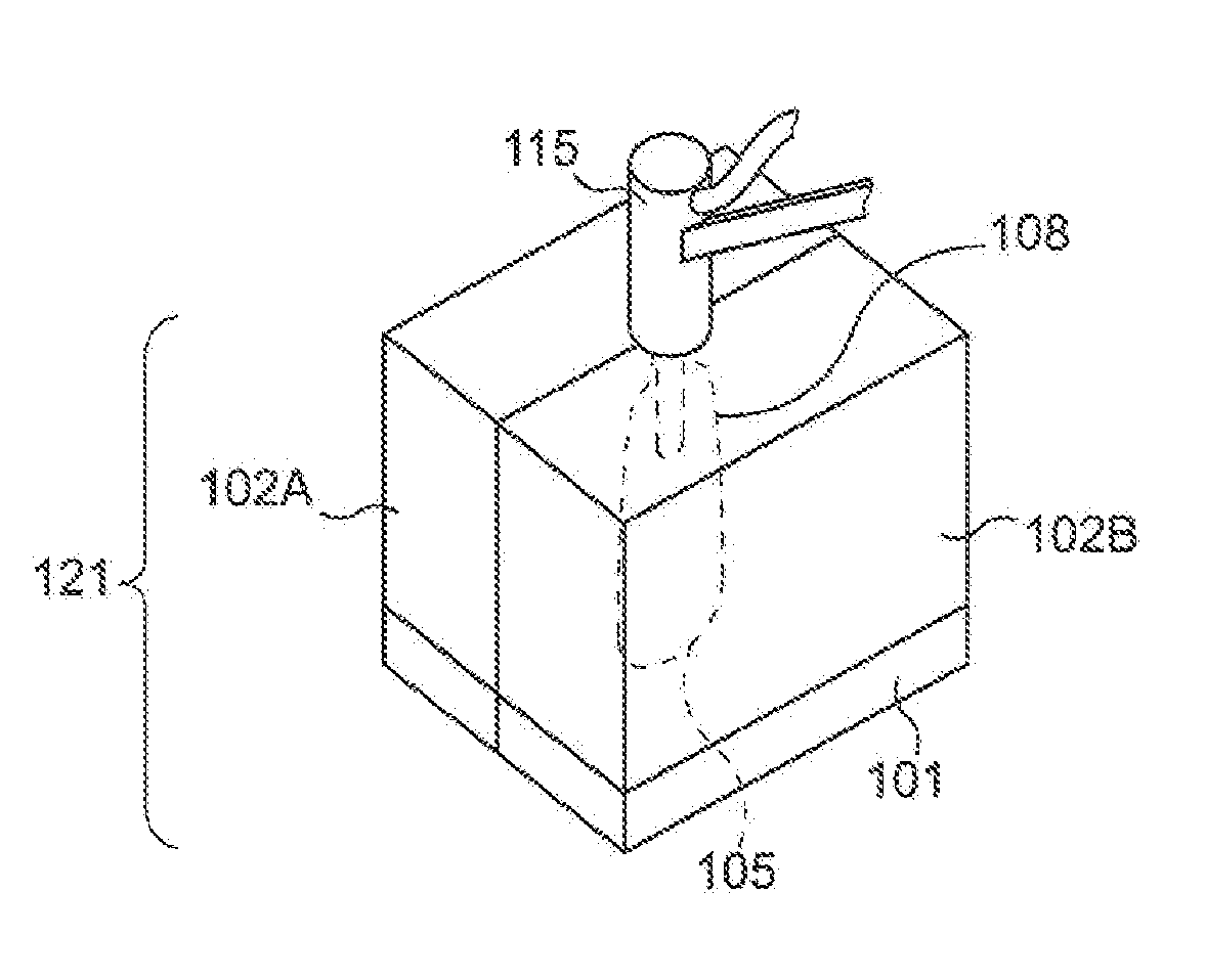
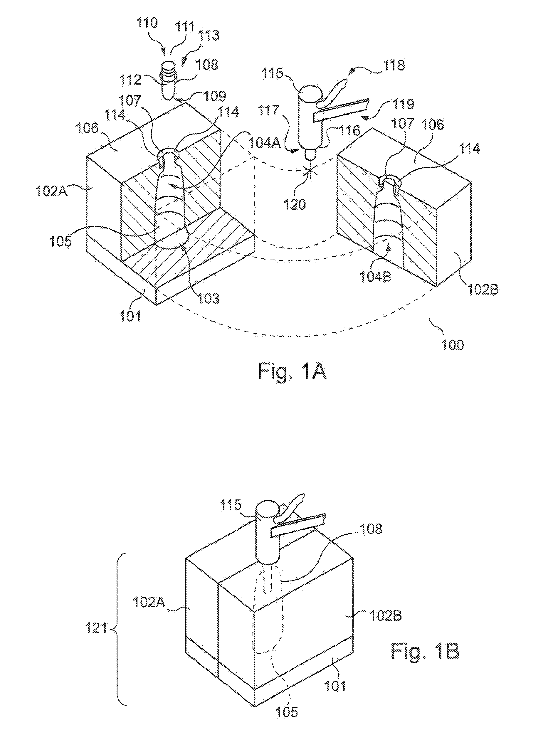
[0032]FIGS. 1A and 1 B are perspective views of an exemplary stretch blow molding apparatus 100 according to an embodiment of the invention. FIG. 1A depicts the apparatus in a partially-exploded disposition. The apparatus 100 comprises a base mold segment 101 and the two lateral mold segments 102A and 102B. The base mold segment 101 is provided with a base depression 103 substantially defining the base of a container, while the lateral mold segments 102A and 102B are respectively provided with the lateral depressions 104A and 104B, each substantially defining half of the body of a container. The base depression 103 and lateral depressions 104 together form the mold cavity 105, which substantially defines the form of a container.

[0033]The lateral depressions 104A and 104B each communicate with a top face 106 of their respective lateral mold segments 102A and 102B, cooperating to form a mold hole 107 communicating with the mold cavity 105. Into the mold hole 107 is disposed a preform ...


PUM

PropertyMeasurementUnit
displacementaaaaaaaaaa
volumeaaaaaaaaaa
pressureaaaaaaaaaa

Abstract

An apparatus for the fabrication of a container (300), comprising a mold defining the form of said container (300) and configured to accommodate a substantially tubular preform, an injection head (115) configured to interface with the preform and establish fluid communication with a cavity thereof; an injection valve (202) configured to selectively permit fluid communication through said injection head (115), and a stretching rod (117) slideably disposed within the injection head (115); said apparatus (100) further comprising a displacement plunger (209) being disposed coaxially about and mobile relative to said stretching rod (117) between a retracted position substantially within the injection head (115) and an extended position wherein said displacement plunger (209) projects at least partially from said injection head (115).

Description

CROSS-REFERENCE TO RELATED APPLICATION[0001]This application is the U.S. national phase of PCT Application No. PCT / EP2013 / 075628 filed on Dec. 5, 2013, which claims priority to EP Patent Application No. 12198181.5 filed on Dec. 19, 2012, the disclosures of which are incorporated in their entirety by reference herein.FIELD OF THE INVENTION[0002]The present invention concerns generally to an apparatus for the fabricating and filling of containers. The invention also relates to a method of employing said apparatus to fabricate and fill containers, as well as the container so produced.BACKGROUND OF THE INVENTION[0003]It is commonly known in the art of container fabrication to fabricate containers by the stretch blow molding process. In the stretch blow molding process, a substantially tubular parison or “preform” is provided, being fabricated from a thermoplastic and having an open end near a mouth and a closed end opposite the open end. The preform is disposed within a mold having a ca...

Claims


Application Information

Patent Timeline
Patent Type & Authority Applications(United States)
IPC IPC(8): B65B3/02B65B39/12B65B3/12
CPCB65B3/022B65B39/12B65B3/12B29L2031/7158B29C49/06B29C49/4289B29C49/46B29C2049/4664B29C2049/4892B29C2049/4294B65B3/26B29C49/12B29C2949/0715
Inventor CHAUVIN, GUILLAUMEKANNENGIESSER, DAMIENCOLLIN, CHIRSTOPHEOUTREMAN, JEAN-TRISTANPELLEGATTA, JEAN-LOUIS
Owner DISCMA
Why Eureka
Try Eureka