
Optical inspection device

a technology of optical inspection and inspection device, which is applied in the direction of instruments, character and pattern recognition, computing, etc., to achieve the effect of simple assembly operation and easy judging

Inactive Publication Date: 2006-06-08
MORITEX CORP
View PDF7 Cites 21 Cited by
  • Summary
  • Abstract
  • Description
  • Claims
  • Application Information

AI Technical Summary

Benefits of technology

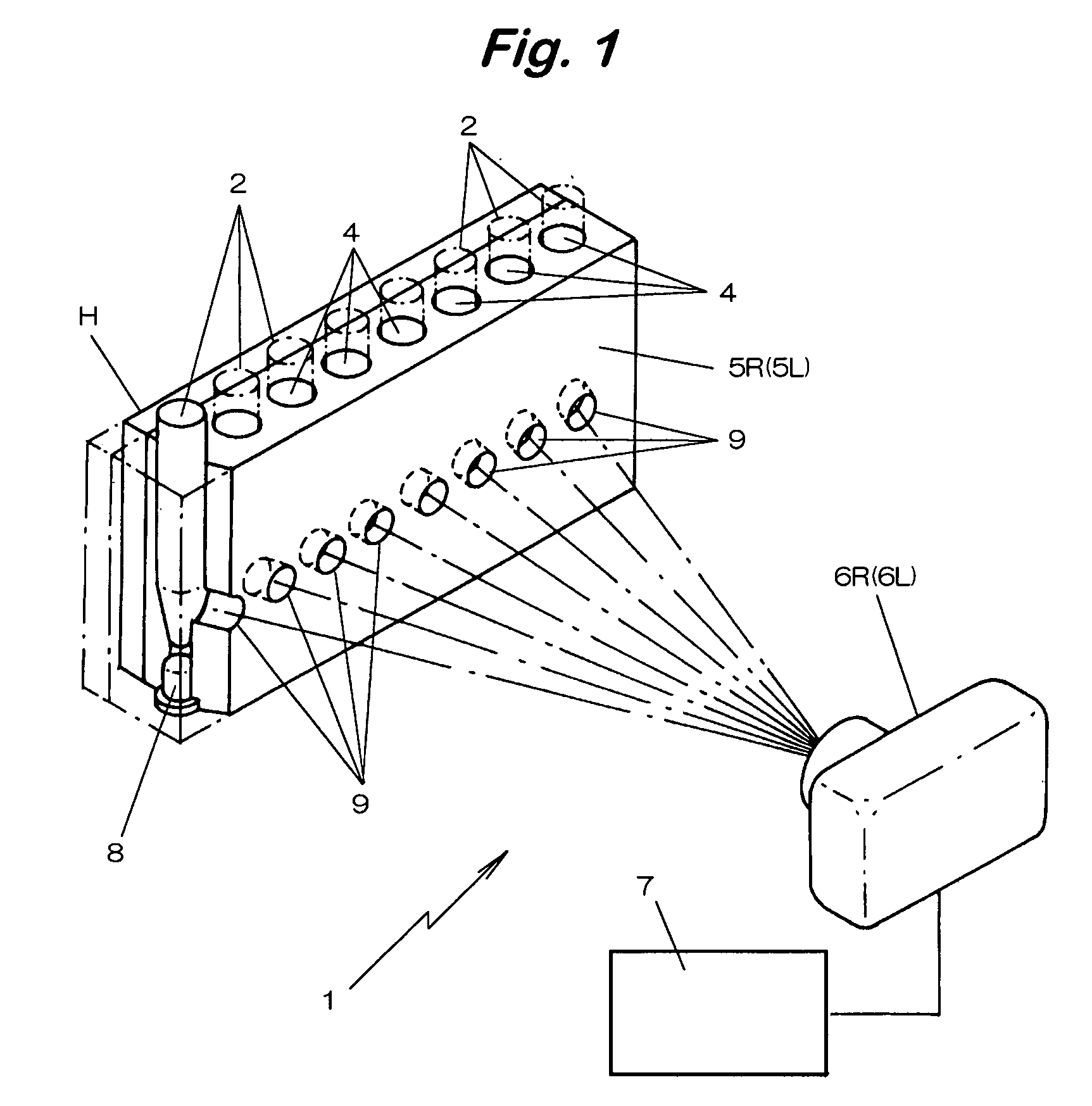
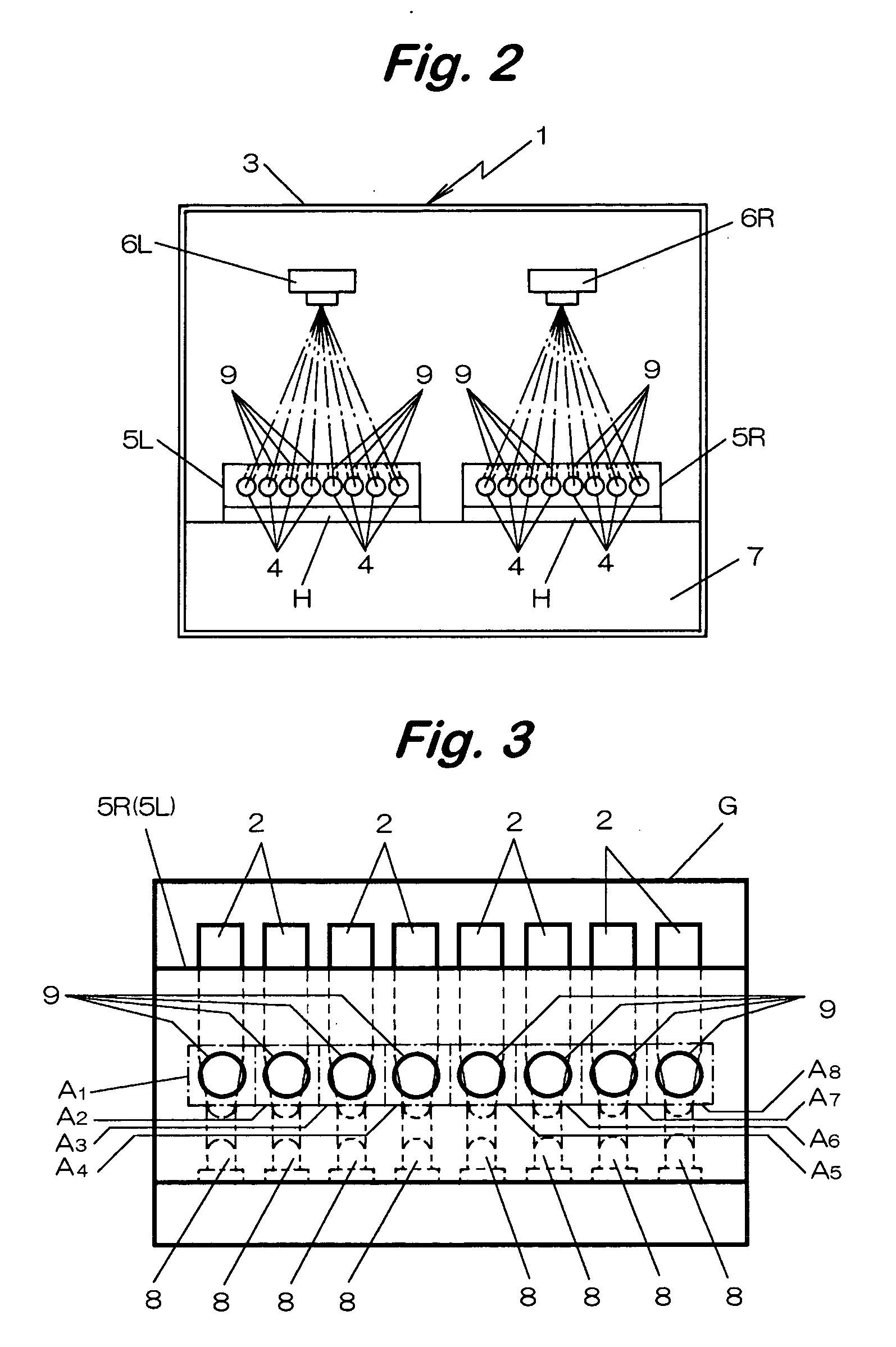
[0023] In this case, since all of the sample tubes can be photographed simultaneously by the image pick-up camera, presence or absence of white turbidity can be detected in each of areas by specifying the areas in the images corresponding to the positions for the observation holes and it can be judged easily which sample causes white turbidity.
[0025] Accordingly, even when the amount of light illuminating each of the sample tubes may change somewhat, the effect due to the change of the light amount can be eliminated by applying image processing so as to properly select a threshold value or conduct normalization and the progressing state of white turbidity and white sedimentation can be detected exactly.
[0026] From the foregoings, even when the amount of light changes under the effect of heat, the turbidity can be detected accurately by attaching the light emitting devices at the bottom of the arrangement holes integrally with the reaction block, and the alignment of the optical axes is not necessary in a case where the light emitting devices are attached integrally with the reaction block.
[0027] Further, since it may suffice for the image pick-up camera that it is situated at a position where all the sample tubes are with in the view field and, whether the position for installation is appropriate or not can be confirmed extremely easily by merely observing the images, accurate alignment for the optical axis of the camera is not necessary at all to simplify the assembling operation of the device.
[0031] In this case, since all of the sample tubes can be photographed simultaneously by the image pick-up camera, it can be judged easily which sample emits fluorescence. Further, since the data of the luminance distribution or chromaticity distribution read from the image data are recognized as the three dimensional information as described above, even when the amount of light irradiating each of the sample tubes changes somewhat, the effect due to the change of the amount of light can be eliminated and the progress of the fluorescent reaction can be detected exactly.
[0032] Further, accurate alignment for the optical axis of the camera is no more necessary at all and the assembling operation of the apparatus can be simplified in the same manner as described above.

Problems solved by technology

Further, as the gene amplification proceeds and the sample causes white turbidity and white sedimentation, since the light irradiated form below scatters in the sample tube, the scattered light leaks through the observation hole and, accordingly, it appears bright when photographed by the image pick-up camera.

Method used


Image

  • Optical inspection device
  • Optical inspection device
  • Optical inspection device

Examples


Embodiment Construction

[0040] A best embodiment according to the present invention is to be described by way of appended drawings.

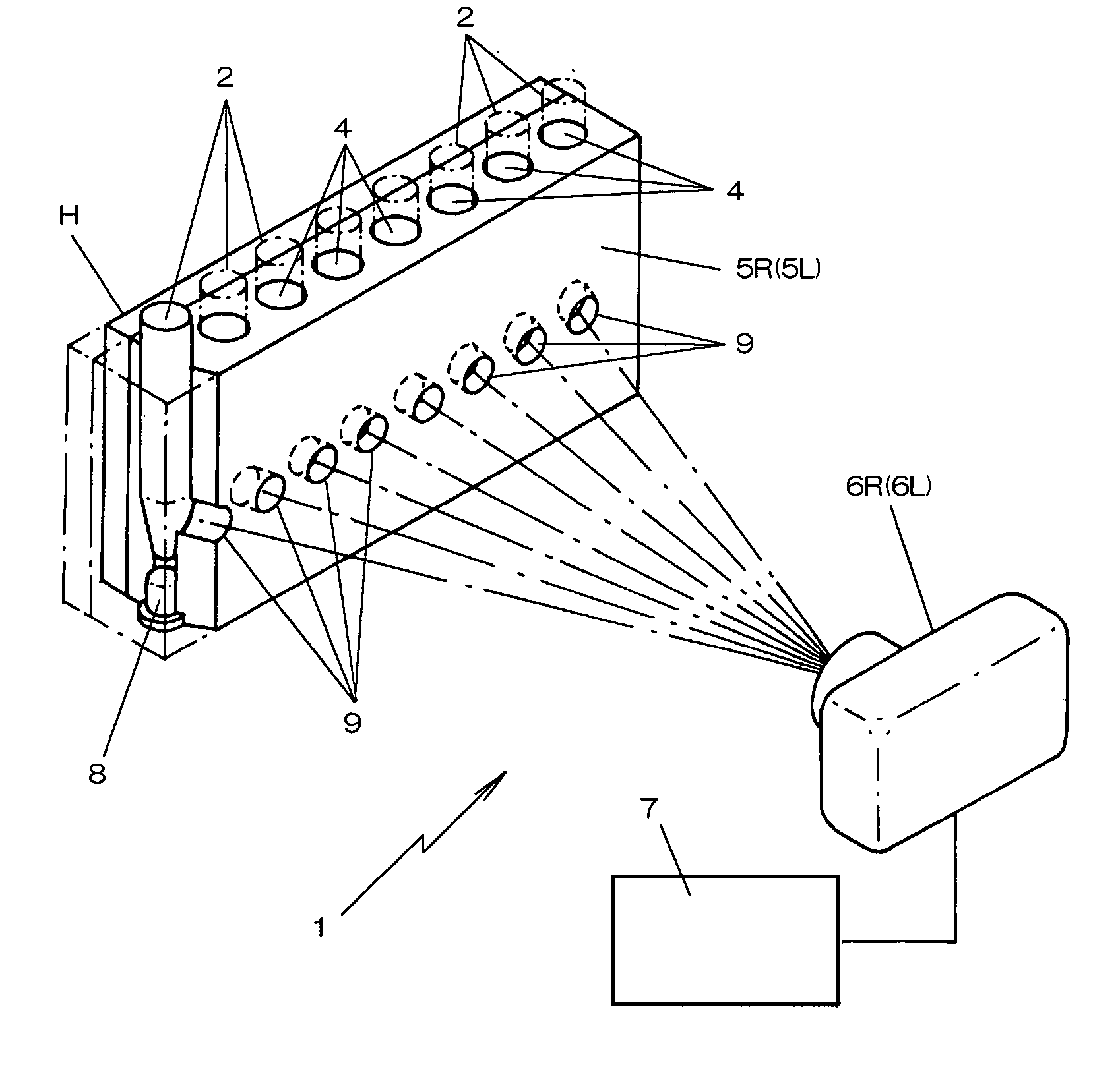
[0041] An optical inspection apparatus 1 shown in FIG. 1 is adopted to optically inspect samples in sample tubes 2,—for the presence or absence of a specified gene of pathogenic bacteria to be inspected (object to be inspected) by the turbidity thereof.

[0042] The optical inspection apparatus 1 includes, in housing 3, two reaction blocks 5R and 5L each having a plurality of arrangement holes 4,—in a lateral row for standing and arranging sample tubes 2,—two sets of image pick-up cameras 6R and 6L for photographing the sample tubes 2 on every reaction blocks 5R and 5L, and an operation processing device 7 for measuring the change of turbidity (optical change) caused in each of the sample tubes based on the luminance distribution or chromaticity distribution of the image data photographed by the image pick-up cameras 6R and 6L.

[0043] In each of the reaction blocks 5R and 5L, a ...


PUM

PropertyMeasurementUnit
ODaaaaaaaaaa
ODaaaaaaaaaa
ODaaaaaaaaaa

Abstract

In the optical inspection apparatus according to the invention, in a case where an optical change such as white turbidity and white sedimentation, or fluorescence is caused to a sample accompanying the reaction of amplifying an object to be inspected present in a sample tube, sample tubes are stood and arranged in a plurality of arrangement holes formed in a reaction block, an inspection light is irradiated to the respective sample tubes passing through the observation holes formed to the lateral surface or the holes formed in the bottom and optical change such as white turbidity and white sedimentation or fluorescence caused in the sample tube are detected based on the luminance distribution or the chromaticity distribution of image data photographed by the image pick-up camera thereby enabling accurate and rapid inspection for the presence or absence of an object to be inspected.

Description

TECHNICAL FIELD [0001] The present invention concerns an optical inspection apparatus for inspecting the presence or absence of an object to be inspected that causes optical change such as white turbidity and white sedimentation, or fluorescence for a sample charged in a sample tube. BACKGROUND ART [0002] In the fields of biochemistry, medicine and pharmacy, foodstuffs, etc., simple, rapid, accurate and inexpensive gene amplification methods have been demanded and an LAMP method has been noted in recent years as a novel gene amplification method capable of satisfying such a demand. [0003] The LAMP method not only shows an extremely high amplification efficiency but also forms a great amount of magnesium pyrophosphate as a byproduct formed by coupling of pyrophosphate ions liberated from a substrate (dNTPs) and magnesium ions in a reaction solution upon elongation synthesis of genes (DNA) in a sample tube, and white turbidity and white sedimentation are observed in the sample tube. [...

Claims


Application Information

Patent Timeline
Patent Type & Authority Applications(United States)
IPC IPC(8): G06K9/00G01N21/82
CPCG01N21/82
Inventor MYOGADANI, TORUTATSU, MASAYOSHI
Owner MORITEX CORP
Learn More