Low-noise loop filter for a phase-locked loop system

a low-noise loop and filter technology, applied in the direction of automatic control, electrical equipment, etc., can solve the problems of lack of flexibility in controlling the loop time constant, the noise of the loop circuit in the mixed-signal integrated circuit design is typically noisy, and the noise is introduced

Active Publication Date: 2006-02-14
CIRRUS LOGIC INC
View PDF3 Cites 29 Cited by
  • Summary
  • Abstract
  • Description
  • Claims
  • Application Information

AI Technical Summary

Problems solved by technology

PLL circuits in mixed-signal integrated circuit designs typically operate in noisy environments.
Much of the noise is introduced through the current or voltage supplies, the substrate, temperature variations, process parameters, or other such sources.
Passive loop filters for PLL circuit designs are popular due to their simplicity, but the control of their loop time constants lacks flexibility.
However, fully differential charge pumps require increased on-chip capacitance and extra circuitry for common mode feedback.
One drawback of a charge pump PLL circuit is that setting the loop filter pole position requires a compromise between the loop phase margin and the jitter performance.
The signal in lock is characterized by narrow high amplitude pulses, that even after filtering, lead to an abrupt variation of the oscillator control signal and rapid frequency changes that degrade the jitter performance of the PLL circuit.
The charge pump loop filter typically has another one-pole filter that helps remove high frequency “noise”, but the addition of this other one-pole filter negatively affects the phase response of the closed loop.
However, the component structures and operations of proportional path 207 and integral path 211 can be fairly complex and involved.

Method used


Image

  • Low-noise loop filter for a phase-locked loop system
  • Low-noise loop filter for a phase-locked loop system
  • Low-noise loop filter for a phase-locked loop system

Examples


Embodiment Construction

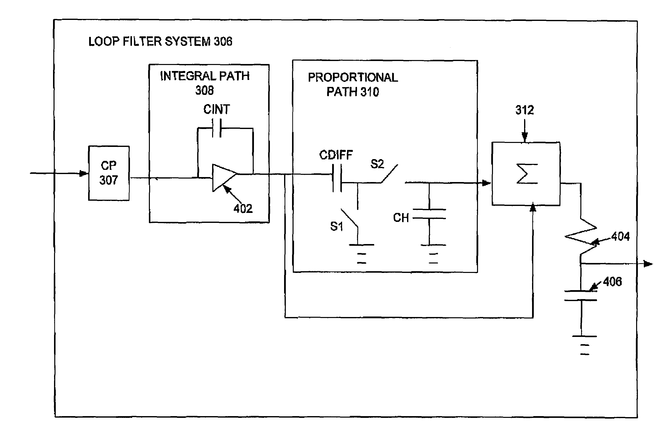
[0023]A loop filter device and method for a phase locked loop (“PLL”) circuit, which locks a frequency of a signal to a reference frequency, are disclosed. The loop filter includes an integral path circuit and a new proportional path circuit cascaded together in series and further includes a summer.

[0024]It is well known in the art that signals for a PLL circuit can be either voltage signals or current signals. Conversion between the voltage and current domains can be performed. Therefore, a PLL circuit could be described as a system having either a respective voltage or current mode filter and either a respective voltage or current controlled oscillator.

[0025]With reference now to FIG. 3, an exemplary phase-locked loop (“PLL”) circuit 300 according to the present invention is shown. PLL circuit 300 includes a phase frequency comparator (“PFC”) 304, a loop filter system 306 that includes a current summer (“Σ”) 312, and a current controlled oscillator (“ICO”) 314 coupled together in ...


PUM


Abstract

A loop filter device and method for a phase locked loop (“PLL”) circuit, which locks a frequency of a signal to a reference frequency, are disclosed. The loop filter includes an integral path circuit and a new proportional path circuit cascaded together in series and further includes a summer. The integral path circuit integrates a loop filter input signal to provide an integrated signal that tracks an overall input signal level. The new proportional path circuit differentiates the integrated signal to provide a proportional signal based on a detected instantaneous phase difference for locking a frequency of a signal for a phase locked loop (PLL) circuit to a reference frequency. The summer receives as inputs and sums the integrated signal and the proportional signal to provide a low-noise loop filter output signal.

Description

BACKGROUND OF THE INVENTION[0001]1. Field of the Invention[0002]The present invention relates to phase-locked loop (“PLL”) circuits, and, more particularly, to a loop filter for a PLL circuit. More specifically, the present invention relates to a low-noise loop filter for a PLL circuit.[0003]2. Description of Related Art[0004]A phase-locked loop (“PLL”) circuit generally includes a phase detector, a loop filter, and a controlled oscillator. The phase detector receives an input signal, which has a reference frequency. The output signal of the controlled oscillator is fed back to the phase detector. The frequency of the output signal is typically a multiple of the reference frequency of the input signal. The PLL circuit is utilized to lock the output frequency to the input frequency. Locking the output frequency to the input reference frequency is critical in various applications, such as developing accurate and precise clocks for digital signal processors (“DSPs”) and for audio sampl...

Claims


Application Information

Patent Timeline
Patent Type & Authority Patents(United States)
IPC IPC(8): H03L7/00H03L7/089H03L7/093H03L7/18
CPCH03L7/093H03L7/0891H03L7/18
Inventor MELANSON, JOHN L.
Owner CIRRUS LOGIC INC
Why Eureka
Try Eureka