Optical disk apparatus

Inactive Publication Date: 2006-02-14
TEAC CORP
View PDF5 Cites 7 Cited by
  • Summary
  • Abstract
  • Description
  • Claims
  • Application Information

AI Technical Summary

Benefits of technology

[0012]It is thus an object of the present invention to provide an optical disk apparatus which is capable of easily ad

Problems solved by technology

When the recording density per unit area is increased in such systems, such optical disk apparatuses suffer from a problem that signal amplitudes are reduced, especially in a high frequency region (near 3T), and the error rate therefore increases.
However, such boosting contributes to a time delay near the 3T, thereby an additional phase difference corresponding to the delay is caused and added to the original jitter amount.
Thus the problem remains that the amount of jitter

Method used


Image

  • Optical disk apparatus
  • Optical disk apparatus
  • Optical disk apparatus

Examples


Example

[0020]A preferred embodiment of the invention will be described below with reference to the drawings.

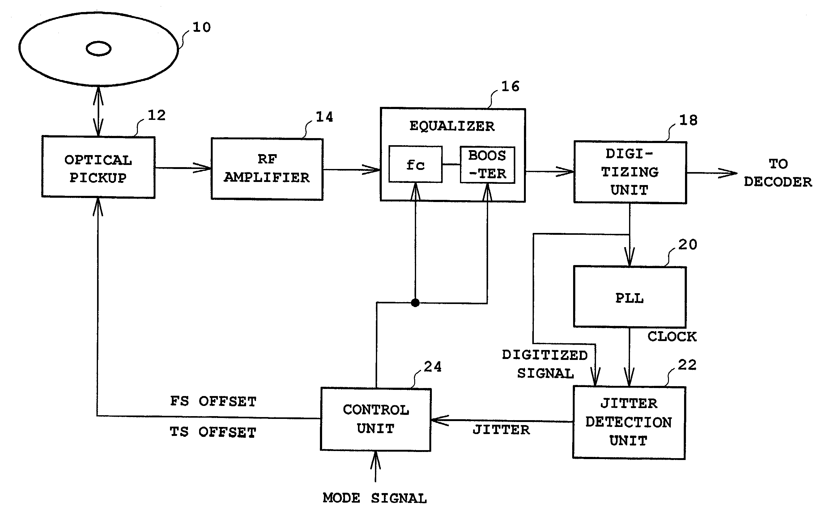
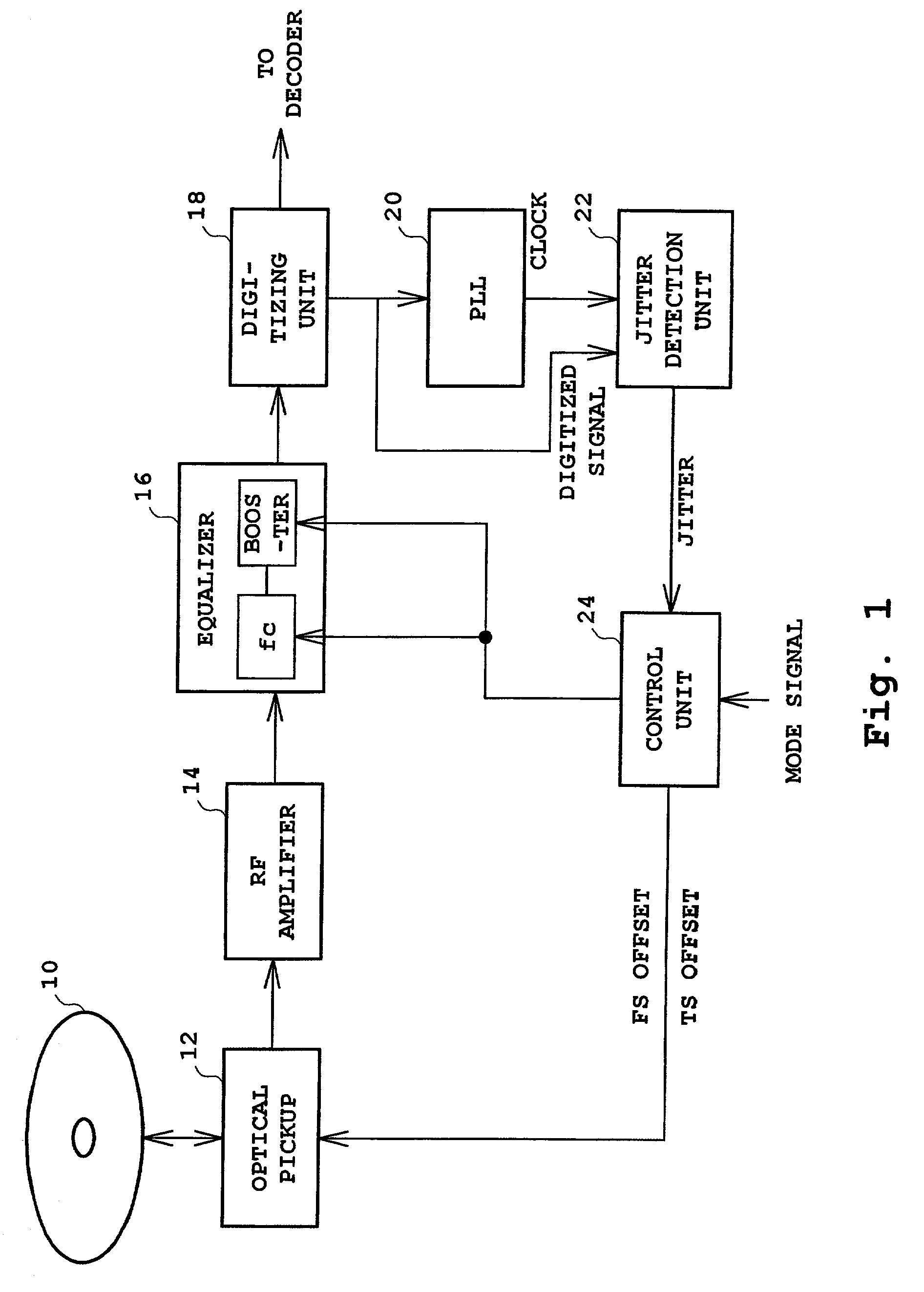
[0021]FIG. 1 shows a block diagram showing a configuration of an optical disk apparatus of the present invention. An optical disk 10, such as a CD, a CD-R, a CD-RW, a DVD, or the like, is rotationally driven at a constant linear velocity (CLV) or at a CAV (Constant Angular Velocity) by a driver not shown in the diagram.

[0022]An optical pickup 12 contains a laser diode (LD) for irradiating a laser beam onto the optical disk and a photodetector for receiving the laser beam reflected from the optical disk, and converts the reflected light into an RF signal and outputs the resultant signal. If the optical disk 10 is a recordable media such as a CD-R, data is recorded by forming pits on the surface of the optical disk 10 by irradiating a more powerful laser beam from an LD during recording than during playback. The optical pickup 12 comprises a focusing actuator for driving an objective l...


PUM


Abstract

An optical disk apparatus capable of adjusting a focus servo and the like by precisely detecting a jitter amount. Light reflected from an optical disk is converted into an RF signal in an optical pickup and amplified by an RF amplifier before being supplied to an equalizer. The boost amount of the equalizer is set to zero during adjustment and set to a predetermined finite value (e.g., +20 dB) during normal recording and reproducing. By first setting the boost amount to zero, the delay characteristics of the RF signal from 3T to 11T are flattened such that an accurate jitter amount can be determined based on the integrated value of the phase differences of 3T to 11T, thereby allowing the optical pickup to be adjusted so as to minimize the jitter amount.

Description

BACKGROUND OF THE INVENTION[0001]1. Field of the Invention[0002]The present invention relates to an optical disk apparatus, and particularly to a technique for performing a gain adjustment using an equalizer on an RF signal read by an optical pickup.[0003]2. Description of the Related Art[0004]Related Art[0005]Optical disk apparatuses for driving an optical disk, such as a CD (compact disk), a CD-R (compact disk-recordable), a CD-RW (compact disk-rewritable) and a DVD (digital versatile disk), are known. An optical disk apparatus reproduces data recorded on a disk by irradiating laser light onto the disk from an LD (laser diode) and converting the light reflected from the optical disk surface into an electric signal (RF signal). When the recording density per unit area is increased in such systems, such optical disk apparatuses suffer from a problem that signal amplitudes are reduced, especially in a high frequency region (near 3T), and the error rate therefore increases.[0006]Thus,...

Claims


Application Information

Patent Timeline
IPC IPC(8): G11B7/00G11B7/005G11B7/004G11B7/09
CPCG11B7/0945G11B7/094G11B7/004
Inventor MASHIMO, AKIRATAKAYAMA, CHISATOUENO, KEISHI
Owner TEAC CORP
Why Eureka
Try Eureka