Methods and systems for reducing waiting-time jitter

Active Publication Date: 2007-03-08
CIENA
View PDF14 Cites 4 Cited by
  • Summary
  • Abstract
  • Description
  • Claims
  • Application Information

AI Technical Summary

Benefits of technology

[0022] Accordingly, an object of the present invention is to provide methods and apparatus for reducing waiting time jitter.
[0023] Thus, an aspect of the present invention provides, in a system for rate adapting a data signal for transport through a synchronous network, a method of minimizing jitter. A phase difference is measured between a data clock s

Problems solved by technology

However, this mapping technique suffers a limitation in that the FIFO-fill signals 28 and 44 in the Tx and Rx tend to vary in a step-wise manner as stuff bytes are inserted and striped from SPE tributaries.
This causes waiting time jitter in the recovered subscriber signal 50.
However, if the timing of the subscriber signal is critical, such as an HDTV signal or a subscriber-originated SONET signal (e.g. for SONET over SONET applications) the introduced jitter can noticeably degrade the quality of the subscriber's signal.
A limitation of this approach is that it only works for a limited range of tributary data and local clock frequencies.
However, the utility of this approach is still restricted to a very limited set of discrete frequency ratios, and these ratios must be known at the time of i

Method used


Image

  • Methods and systems for reducing waiting-time jitter
  • Methods and systems for reducing waiting-time jitter
  • Methods and systems for reducing waiting-time jitter

Examples


Embodiment Construction

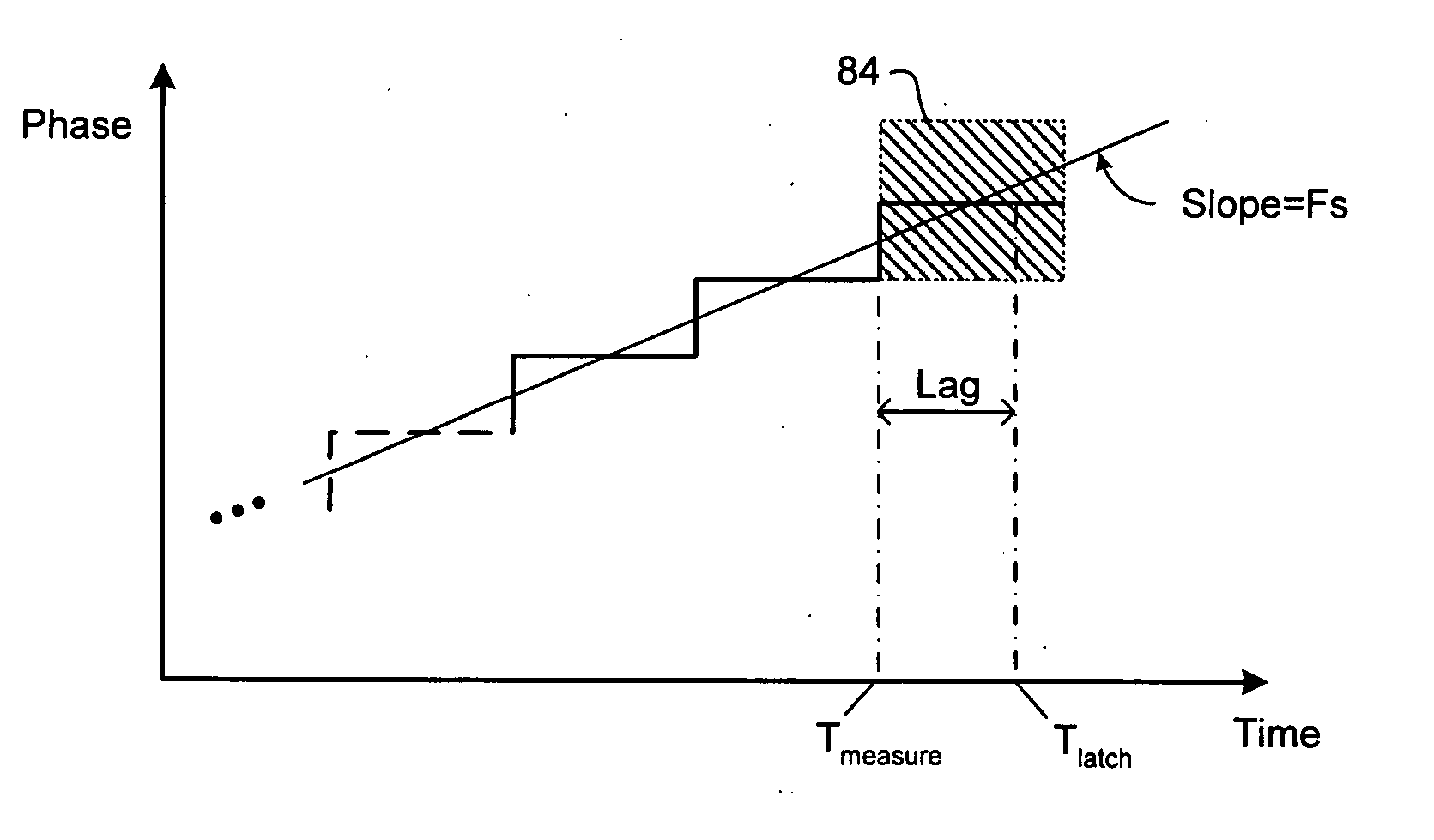
[0034] The present invention provides methods and apparatus for reducing jitter by minimizing the effects of phase measurement ambiguities. Embodiments of the invention are described below, by way of example only, with reference to FIGS. 5a-9.

[0035] In general, the present invention operates by attenuating (or damping) the response of the timing estimate calculation to phase measurement jitter due to noise and ambiguity, without altering its linear response to larger variations due to the frequency difference (or ratio f1 / f2) between the data clock signal 10 and the Tx local clock signal 26. This technique relies on the observation that the frequency ratio f1 / f2 is dominated by low frequency (e.g. on

[0036] the order of about 10 Hz or lower) variations due to wander or drift of the Tx local clock 22 and the clock recovery circuit 12. On the other hand, ambiguity (i.e. quantization error and lag) of the phase measurement, and noise tend to introduce jitter in the form of low magnitu...


PUM


Abstract

A method of minimizing jitter in a system for rate adapting a data signal for transport through a synchronous network. A phase difference is measured between a data clock synchronous with the data signal and a local clock of the synchronous network. A timing reference (F) indicative of a frequency difference between the asynchronous data signal and the local clock is measured using the measured phase difference. Calculation of the timing reference includes compensating ambiguity in the measured phase difference.

Description

CROSS-REFERENCE TO RELATED APPLICATIONS [0001] This is the first application filed for the present invention. MICROFICHE APPENDIX [0002] Not Applicable. TECHNICAL FIELD [0003] This invention relates to communications networks, and in particular to methods and systems for reducing waiting-time jitter. BACKGROUND OF THE INVENTION [0004] Within the modern network space, the Synchronous Optical Network (SONET) / Synchronous Digital Hierarchy (SDH) protocol is becoming increasingly popular as a mechanism for data transport. In this respect, SDH is the European equivalent of the SONET transmission standard. Accordingly, all references in this application to SONET should be understood to also refer to SDH. [0005] A significant amount of SONET / SDH infrastructure has been installed, particularly within the network core. This SONET infrastructure is used to transport asynchronous subscriber signal traffic having differing formats, such as Asynchronous Transfer Mode (ATM), Internet Protocol (IP)...

Claims


Application Information

Patent Timeline
IPC IPC(8): H04J3/06
CPCH04L1/205H04J3/076
Inventor ROBERTS, KIM B.BONTU, CHANDRAHARLEY, JAMES
Owner CIENA
Why Eureka
Try Eureka