Current mode logic circuit with multiple frequency modes

a logic circuit and multiple frequency mode technology, applied in the direction of generating/distributing signals, pulse techniques, instruments, etc., can solve the problems that the given cml driver may be less suitable for some devices than for other devices, and achieve the effects of reducing power consumption, minimizing jitter, and reducing power consumption

Active Publication Date: 2015-11-19
QUALCOMM INC
View PDF1 Cites 4 Cited by
  • Summary
  • Abstract
  • Description
  • Claims
  • Application Information

AI Technical Summary

Benefits of technology

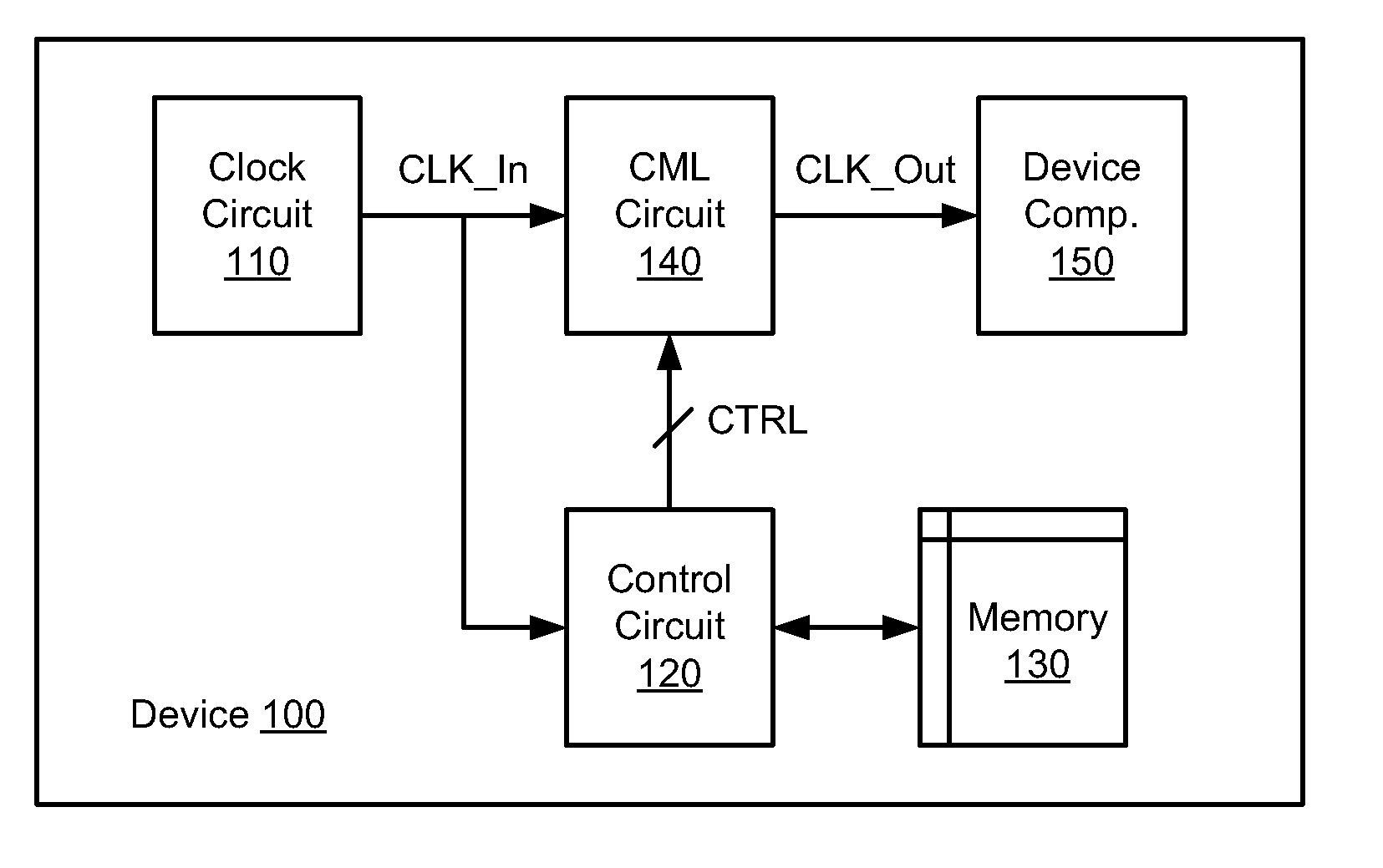
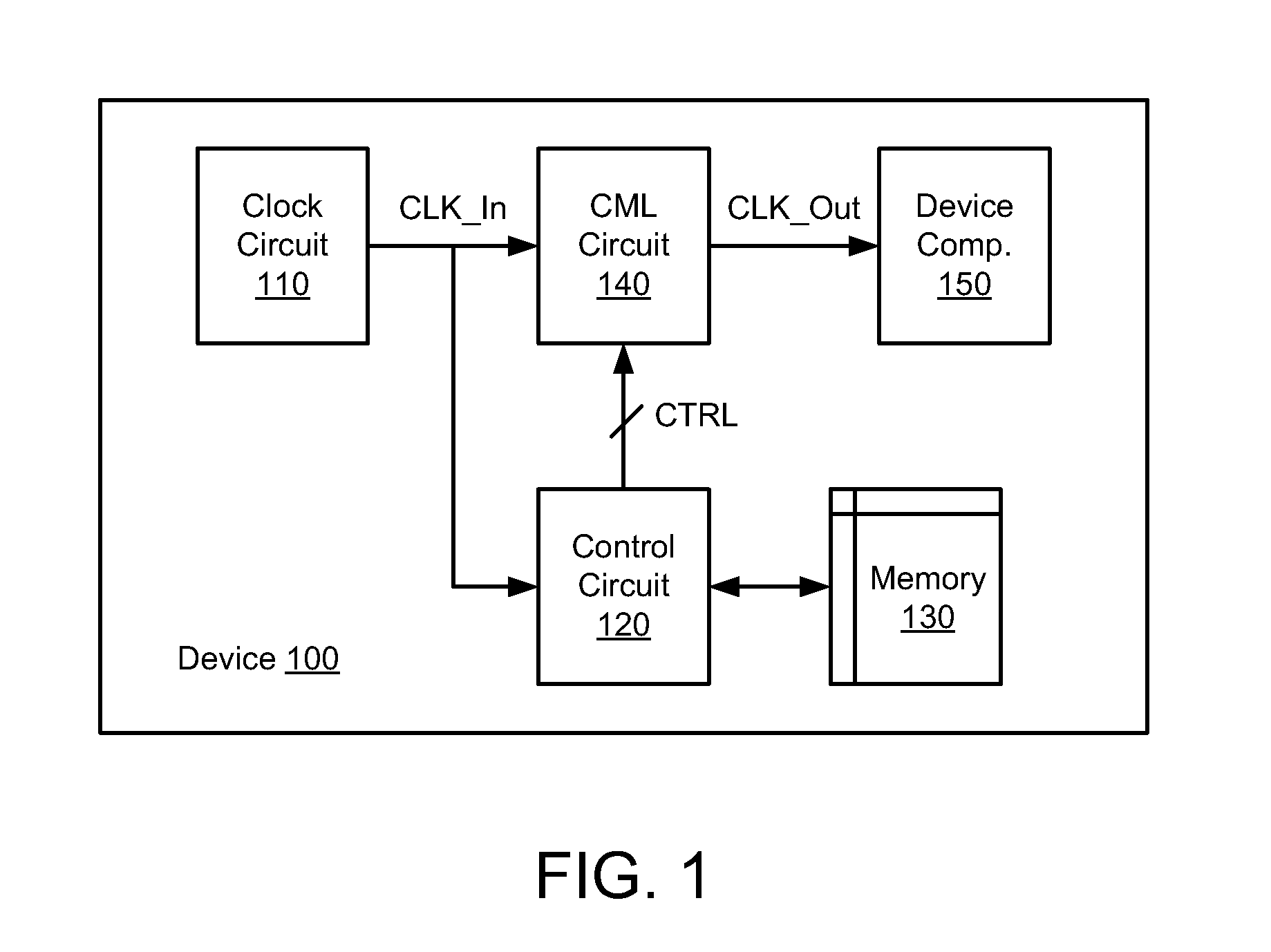
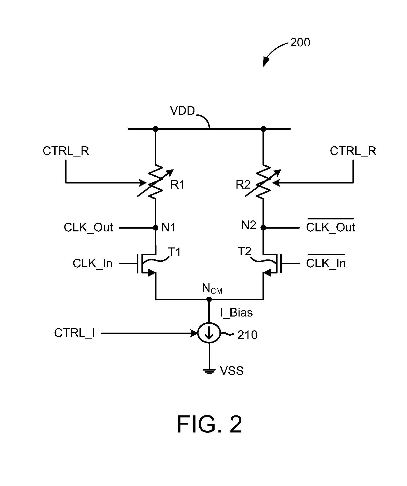
[0008]For example, for a relatively low frequency mode (e.g., for frequencies less than a first threshold value), the bias current may be set to a relatively low value (e.g., to reduce power consumption), and the resistance of the variable resistors may be set to relatively high values (e.g., to offset the relatively low bias current value). For a relatively high frequency mode (e.g., for frequencies greater than a second threshold value), the bias current may be set to a relatively high value (e.g., to minimize jitter associated with higher frequency clock signals), and the resistance of the variable resistors may be set to relatively low values (e.g., to offset the relatively high bias current value). In this manner, the signal amplitude of the second differential clock signal may be maintained at a desired level for different clock frequencies so that power consumption is reduced for low frequency clock signals and jitter is minimized for high frequency clock signals. For some embodiments, the first threshold value and the second threshold value may be the same. For other embodiments, the first threshold value may be less than the second threshold value.

Problems solved by technology

Because different devices may have different data rates and / or different clock speeds, a given CML driver may be less suitable for some devices than for other devices.

Method used


Image

  • Current mode logic circuit with multiple frequency modes
  • Current mode logic circuit with multiple frequency modes
  • Current mode logic circuit with multiple frequency modes

Examples


Embodiment Construction

[0015]In the following description, numerous specific details are set forth such as examples of specific components, circuits, and processes to provide a thorough understanding of the present disclosure. The term “coupled” as used herein means connected directly to or connected through one or more intervening components or circuits. Also, in the following description and for purposes of explanation, specific nomenclature is set forth to provide a thorough understanding of the present embodiments. However, it will be apparent to one skilled in the art that these specific details may not be required to practice the present embodiments. In other instances, well-known circuits and devices are shown in block diagram form to avoid obscuring the present disclosure. Any of the signals provided over various buses described herein may be time-multiplexed with other signals and provided over one or more common buses. Additionally, the interconnection between circuit elements or software blocks...


PUM


Abstract

A device comprising a clock circuit, a control circuit, and a current mode logic (CML) circuit is disclosed. The clock circuit provides a first differential clock signal and the control circuit generates a control signal based at least in part on the frequency of the first differential clock signal. The CML circuit generates a second differential clock signal based at least in part on the first differential clock signal. The CML circuit operates in one of a plurality of different frequency modes based at least in part on the control signal and includes a number of variable resistors that are responsive to the control signal.

Description

TECHNICAL FIELD[0001]The present embodiments relate generally to differential signaling technologies, and specifically to driving differential clock signals at different frequencies.BACKGROUND OF RELATED ART[0002]In serializer / deserializer (SERDES) circuits, a differential signaling scheme commonly referred to as current mode logic (CML) may be used for clock distribution in a device. A typical CML driver may receive an input differential clock signal and provide an output differential clock signal to a variety of components, such as a transmit circuit or receive circuit of the device.[0003]CML drivers typically operate within predetermined frequency ranges. Because different devices may have different data rates and / or different clock speeds, a given CML driver may be less suitable for some devices than for other devices. Thus, it is desirable for the given CML driver to be suitable for a wide range of devices operating over a wide range of data rates and / or clock speeds.SUMMARY[00...

Claims


Application Information

Patent Timeline
Patent Type & Authority Applications(United States)
IPC IPC(8): H03K5/01
CPCH03K5/01H03K19/018514H03K19/09432
Inventor SINGH, GUNEETCRANFORD, JR., HAYDEN CLAVIEFERTSCH, MICHAEL THOMAS
Owner QUALCOMM INC
Why Eureka
Try Eureka