Optical disk device

a technology of optical disk and optical disk, which is applied in the direction of digital signal error detection/correction, instruments, recording signal processing, etc., can solve the problems of jitter value small, signal may sometimes be missing, and difficulty in writing the shortest signal

Inactive Publication Date: 2006-10-03
TEAC CORP
View PDF10 Cites 4 Cited by
  • Summary
  • Abstract
  • Description
  • Claims
  • Application Information

AI Technical Summary

Benefits of technology

[0015]Accordingly, an object of the present invention is to provide an optical disk device in which the writing power can be optimized.
[0018]According to another aspect of the present invention, it is preferable that, in the optical disk device, the means for optimizing selects, as the optimum laser light power, the laser light power at which the jitter of the replayed signal is minimized, and the means for judging increases the jitter of the replayed signal of the test data when the test data is judged to be abnormal. With such a configuration, it is possible to eliminate as a candidate for the optimum laser light power a laser light power for which the test data is judged as abnormal.
[0020]According to another aspect of the present invention, it is preferable that, in the optical disk device, the means for optimizing selects, as the optimum laser light power, the laser light power at which the jitter is minimized, and the means for detecting abnormality increases the jitter when the error rate is greater than or equal to the predetermined value. With such a configuration, it is possible to eliminate, from the candidates for the optimum writing power, the laser light power at which the error rate exceeds the predetermined level.

Problems solved by technology

However, in general, it is difficult to write the shortest signal, the signal with length 3T (“3T signal”), and therefore, the signal may sometimes be missing because of a writing error.
As a result, the jitter value appears to be small although the test data is not normally written, and there had been a problem in that the optimum writing power is selected based on this apparently small jitter value.
However, the 3T (mark) period has a small pulse width and, when the writing power is insufficient, the level of replayed signal may sometimes fall short of the threshold value because a pit is not adequately formed.
Therefore, jitter value for the writing power appears to be smaller than the actual value, and thus, there is a problem in that although in reality, the writing power is insufficient, this power may be erroneously determined as the optimum writing power.
Because in OPC, the writing power with minimum jitter value is determined as the optimum writing power, a writing power may be erroneously determined as the optimum writing power even when the writing power is actually excessive.
In this case, the writing power where the jitter value is minimized cannot be calculated, and a writing power which is smaller than the actual optimum writing power or a writing power which is greater than the actual optimum writing power may be erroneously determined as the optimum writing power, resulting in a problem in that the actual data cannot be written with high quality.

Method used


Image

  • Optical disk device
  • Optical disk device
  • Optical disk device

Examples


first embodiment

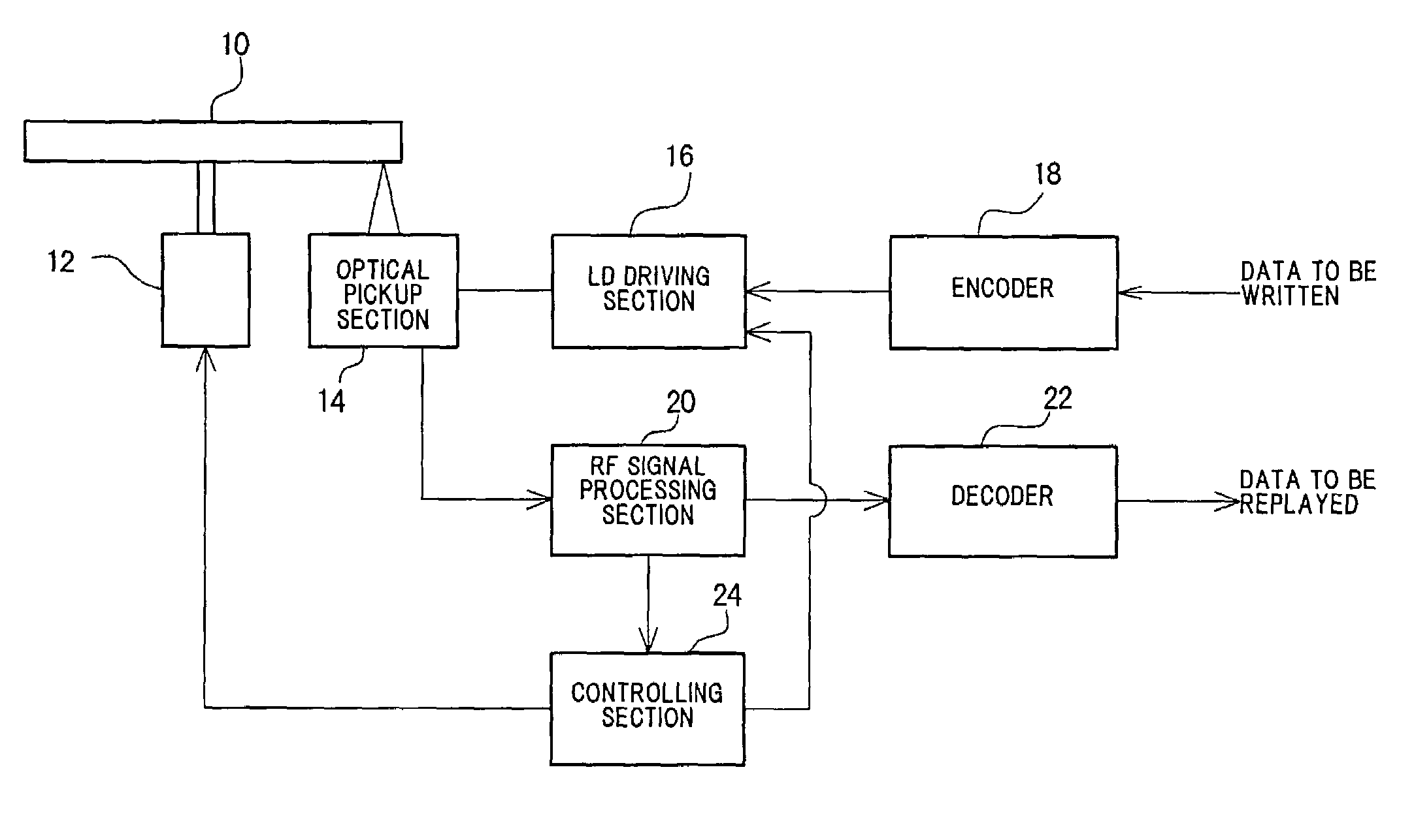
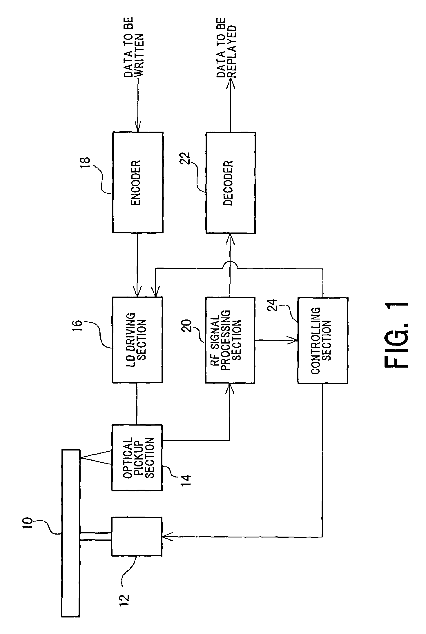
[0056]FIG. 1 is a block diagram showing the significant structures of an optical disk device according to a An optical disk 10 is CAV controlled (or CLV controlled) by a spindle motor 12.

[0057]An optical pickup section 14 provided to oppose the optical disk 10 writes data onto the optical disk 10 by emitting laser light of a writing power from a laser diode (LD). The writing of data may be effected by fusing and subliming a portion of a writing film of the optical disk 10 to form a pit, or, alternatively, by heating and quickly cooling so that the state transitions from a crystalline state to an amorphous state.

[0058]When data is written, the data to be written is supplied to an encoder 18 and the data encoded by the encoder 18 is supplied to an LD driving section 16. The LD driving section 16 generates a drive signal based on the encoded data and supplies the drive signal to the LD of the optical pickup section 14. In addition, a control signal from a control section 24 is supplie...

second embodiment

[0088]In the second embodiment, the abnormality of jitter value is detected when the space value differs from the actual count value and when the abnormality in jitter value is detected, the jitter value is uniformly replaced with a maximum value. However, the present invention is not limited to such a configuration, and it is also possible to reject the jitter value as “NG” (no good) or as immeasurable when the abnormality in jitter value is detected, to thereby remove the writing power from the candidates for the optimum writing power.

[0089]In the above embodiments, the writing power at which the jitter value is minimized is determined as the optimum writing power. However, the present invention is not limited to such a configuration, and can be similarly applied to cases where the optimum writing power is determined based on any other signal quality of the replayed signal such as, for example, the β value.

[0090]Also in the embodiments, the erroneous writing of test data has been ...


PUM

PropertyMeasurementUnit
light poweraaaaaaaaaa
length space periodaaaaaaaaaa
lengthaaaaaaaaaa

Abstract

An optical disk device in which the laser light power for writing data onto an optical disk is optimized. Test data is written onto an optical disk while laser light power is varied and the laser light power is optimized based on the quality of replayed signals of the test data. The space value of the replayed signal of the test data is detected and, when the space value is a value which should not exist, it is judged that 3T mark period is missing or excessively written and the laser light power in which such a space value is obtained is removed from the candidates for the optimum laser light power. Also, jitter and error rate of the replayed signal are detected. Even when the jitter is at a desirable value, if the error rate is greater than or equal to a predetermined value, the laser light power in which such an error rate is obtained is removed from consideration as a possible optimum laser light power.

Description

BACKGROUND OF THE INVENTION[0001]1. Field of the Invention[0002]The present invention relates to an optical disk device, and in particular to optimization of a writing power when data is written onto a recordable optical disk.[0003]2. Description of the Related Art[0004]When data is to be written onto a recordable optical disk such as a CD-R, CD-RW, DVD-R, or DVD-RW disk, test data is repeatedly written as a test in a predetermined region (PCA area) of the optical disk while the writing power is varied, the test data is replayed, a writing power in which the quality of the replayed signal is maximized is selected as the optimum writing power, and the data is written (a process commonly referred to as optimum power control (OPC)).[0005]For example, Japanese Patent Laid-Open Publication No. 2000-137918 discloses such a method in which test data is written as a test in the PCA area of an optical disk while varying the writing power, jitter value of the written test data is measured, an...

Claims


Application Information

Patent Timeline
Patent Type & Authority Patents(United States)
IPC IPC(8): G11B7/00G11B7/0045G11B7/125G11B7/126
CPCG11B7/0045G11B7/126
Inventor TAKEDA, NAOTO
Owner TEAC CORP
Why Eureka
Try Eureka