Signal interconnect with high pass filter

Inactive Publication Date: 2016-12-29
QUALCOMM INC
View PDF0 Cites 4 Cited by
  • Summary
  • Abstract
  • Description
  • Claims
  • Application Information

AI Technical Summary

Benefits of technology

[0015]In some aspects, a capacitance of the first capacitive circuit is selected to maximize a quality of an eye diagram (eye-pattern) associated with a signal carried by the signal interconnect. In some aspects, a capacitance of the first cap

Problems solved by technology

However, active circuits consume a significant amount of power.
Hence, this latter technique is limited by the length of the

Method used


Image

  • Signal interconnect with high pass filter
  • Signal interconnect with high pass filter
  • Signal interconnect with high pass filter

Examples


example implementation

[0058]FIG. 5 illustrates an example implementation for a signal interconnect 502 as taught herein. The signal interconnect 502 couples high speed signals (e.g., 50 Gbps) from a high speed multiplexer 504 to a terminal 506 for off-chip communication. In this example, the chip (e.g., integrated circuit) is a memory device 507 that include four memory ranks 508, 510, 512 and 514. Reads and writes to and from each of the individual ranks are stored in a corresponding one of the registers 516, 518, 520, or 522 for sequential transfer to / from the multiplexer 504. Thus, a high speed data rate (e.g., 50 Gbps) may be employed for memory components (e.g., the memory ranks 508, 510, 512 and 514) that each operate at a lower speed (e.g., 12.5 Gbps).

Other Implementations

[0059]The series impedances, terminator impedances, and the transmission lines discussed above may take different forms in different implementations. FIGS. 6-9 describe three different implementations.

[0060]In FIG. 6, a signal in...

example process

[0066]FIG. 10 illustrates an example process for signal compensation in accordance with the teachings herein.

[0067]At block 1002, a signal is received at a signal interconnect.

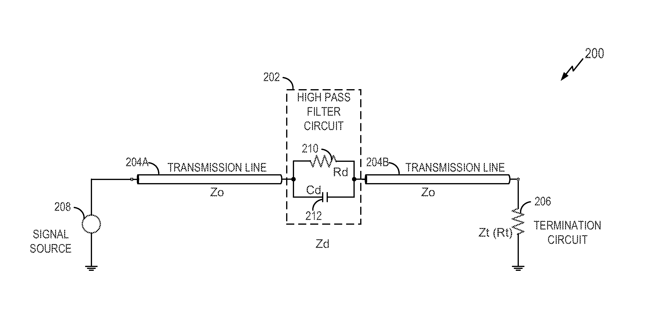
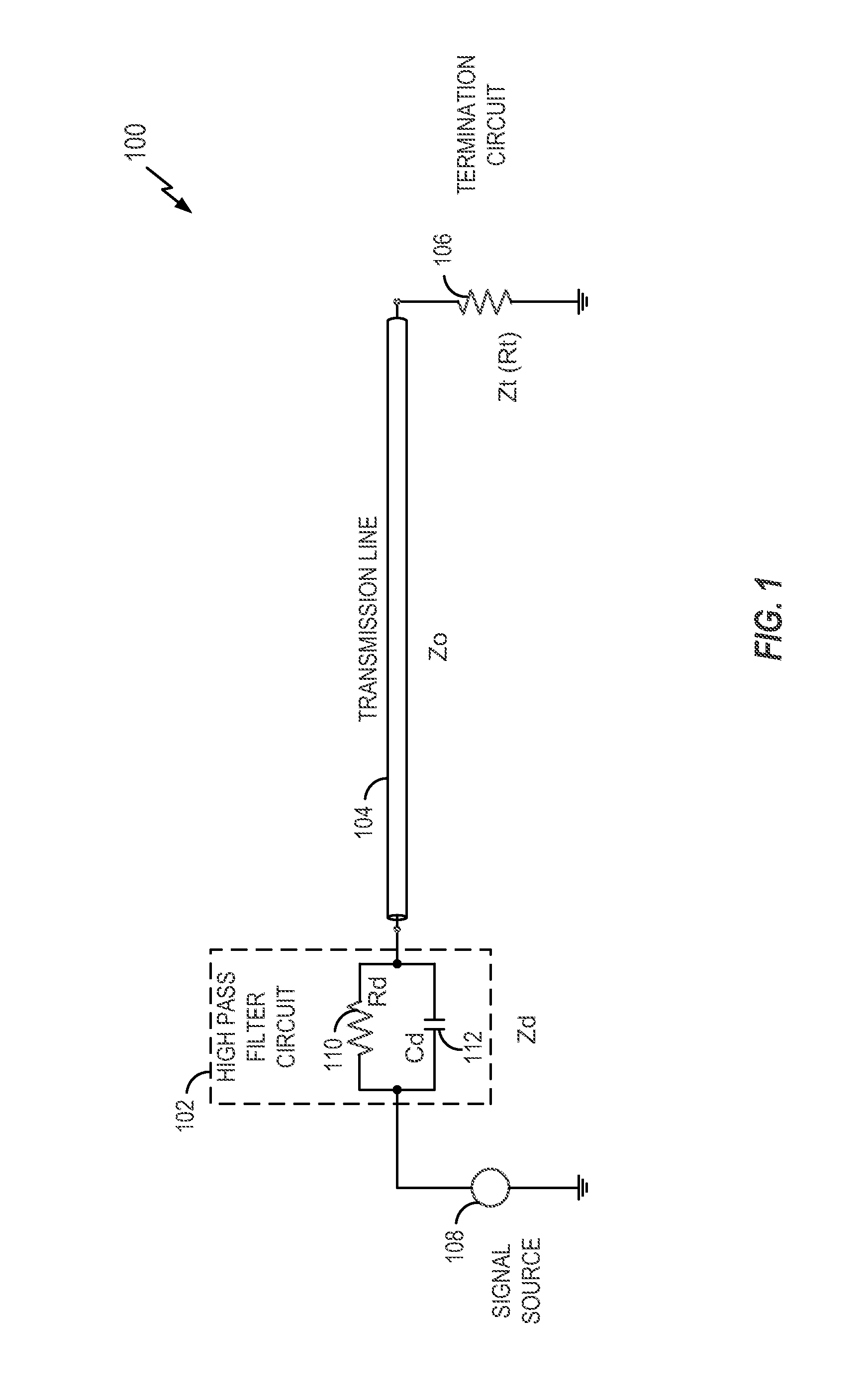
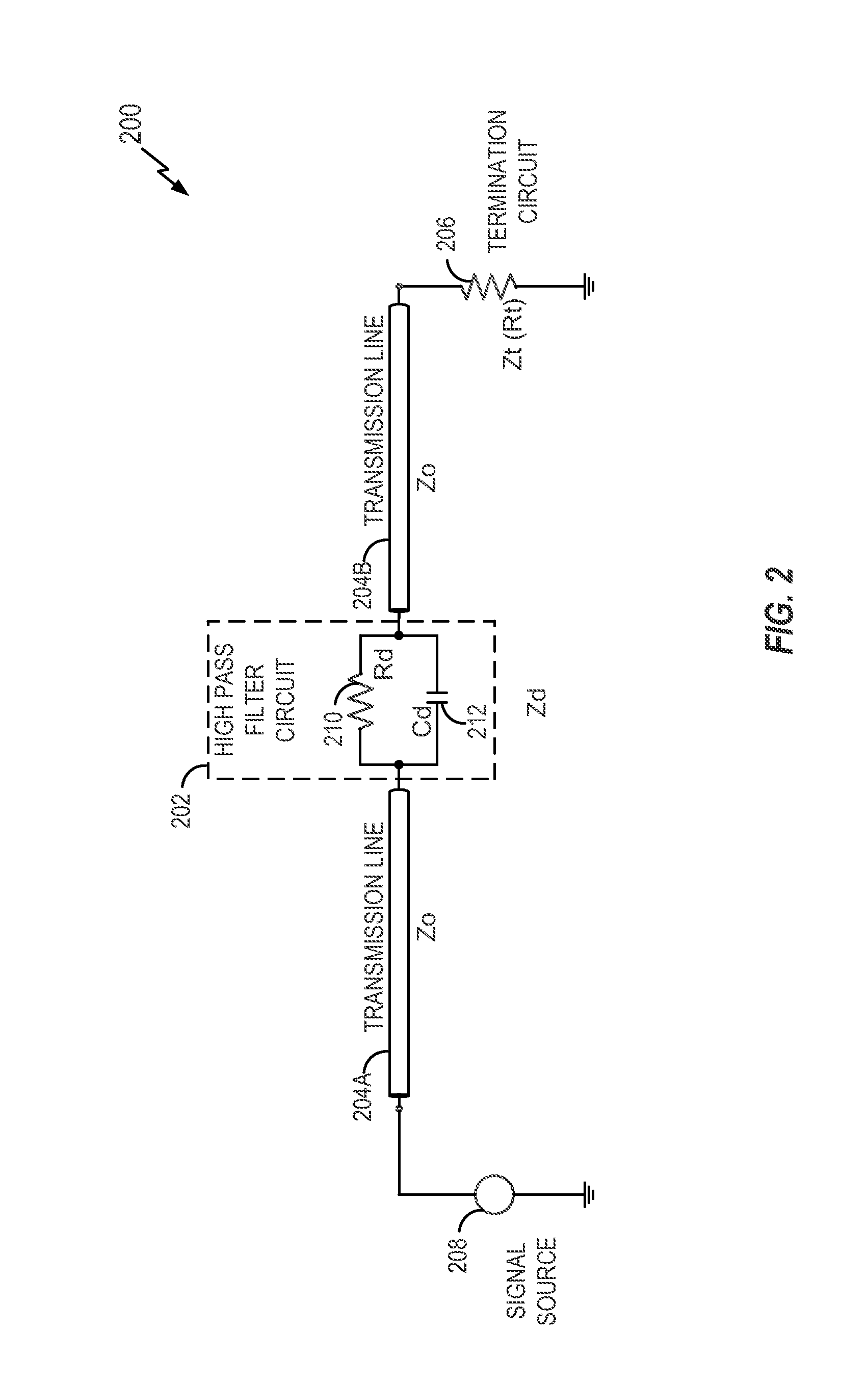
[0068]At block 1004, the signal is high pass filtered. In accordance with the teachings herein, the high pass filter circuit includes a first resistive circuit and a first capacitive circuit coupled in parallel. The first resistive circuit has a resistance based on a difference between a resistance of the transmission line at a high frequency and a resistance of the transmission line at a low frequency.

[0069]At block 1006, the signal passes through a transmission line.

[0070]At block 1008, the signal is terminated at an end of the transmission line.

Additional Aspects

[0071]One or more of the components, steps, features and / or functions illustrated in the figures may be rearranged and / or combined into a single component, step, feature or function or embodied in several components, steps, or functions. Additional ...


PUM


Abstract

A signal interconnect includes a transmission line, a termination circuit coupled to the transmission line, and a high pass filter circuit coupled in series along the transmission line. The high pass filter circuit includes a first resistive circuit and a first capacitive circuit coupled in parallel. The first resistive circuit has a resistance based on a difference between a resistance of the transmission line at a high frequency and a resistance of the transmission line at a low frequency.

Description

BACKGROUND[0001]Field of the Disclosure[0002]Aspects of the disclosure relate generally to electrical circuits, and more specifically, but not exclusively, to a signal interconnect that includes a high pass filter.[0003]Description of Related Art[0004]With the advancement of very large scale integration (VLSI) technology, inter-chip communication is expected to exceed 20 GHz. The design of an inter-chip interconnect that operates at high signaling rates may compensate for high losses, latency, and parasitic effects that occur at these signaling rates. In addition, it is desirable to keep power consumption low even at these high signaling rates.[0005]Some high speed transmission line designs use active pre-emphasis and equalization circuits at the drivers and the receivers. However, active circuits consume a significant amount of power.[0006]Passive compensation is one potential approach to achieve the goal of high speed and low power. With a passive approach (e.g., using passive and...

Claims


Application Information

Patent Timeline
IPC IPC(8): H03H7/01H03H7/00H03H7/06
CPCH03H7/0138H03H7/004H03H7/06H04B3/14H04L25/0278H04L25/0286H04L25/0298H03K19/0005H01P1/24H03H7/07H03H7/0123H03H7/383H04L25/03878
Inventor LIU, CHUNCHENCHEN, PO-HUNGDUAN, ZHENGYU
Owner QUALCOMM INC
Why Eureka
Try Eureka