LED illuminated pendant

a technology of led lights and pendants, applied in the direction of bracelets, lighting and heating devices, lighting support devices, etc., can solve the problems of cumbersome construction and over-complicated construction

Inactive Publication Date: 2006-02-21
AMERICHIP
View PDF3 Cites 17 Cited by
  • Summary
  • Abstract
  • Description
  • Claims
  • Application Information

AI Technical Summary

Problems solved by technology

Unfortunately, the separation of the circuit around a person's neck makes the construction cumbersome and overly complicated.

Method used


Image

  • LED illuminated pendant
  • LED illuminated pendant
  • LED illuminated pendant

Examples


Embodiment Construction

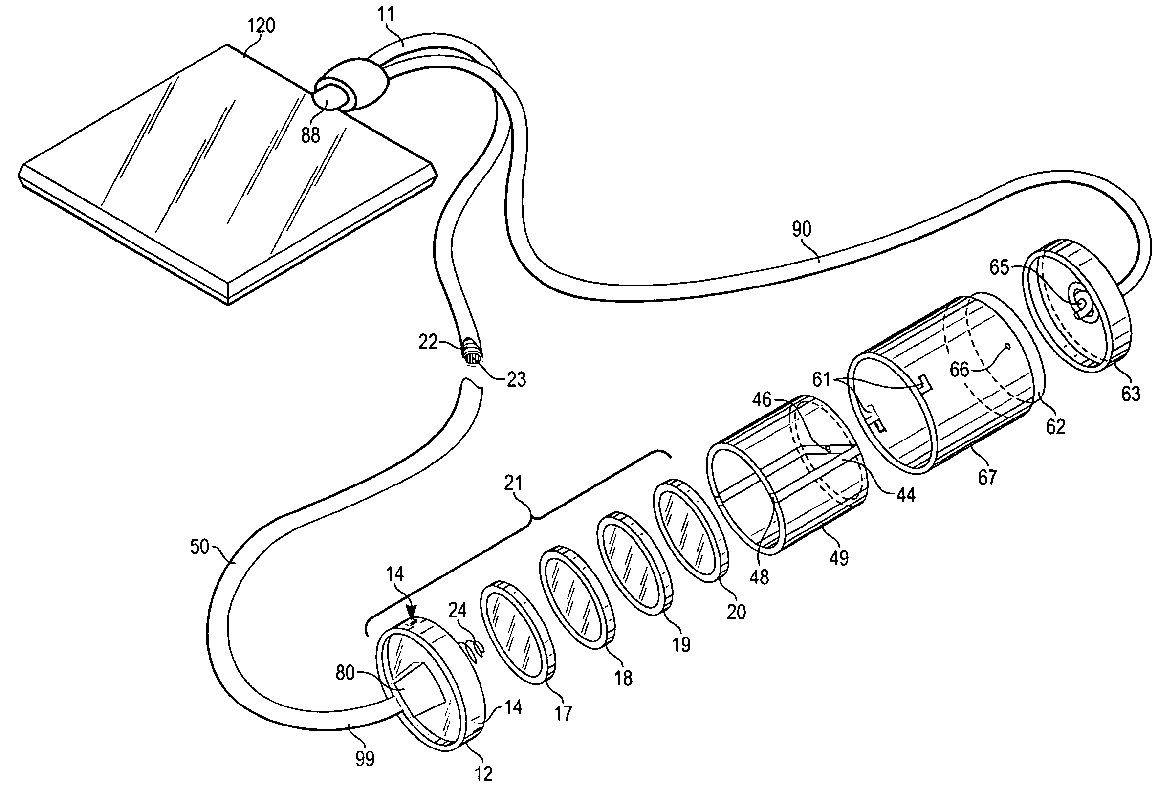
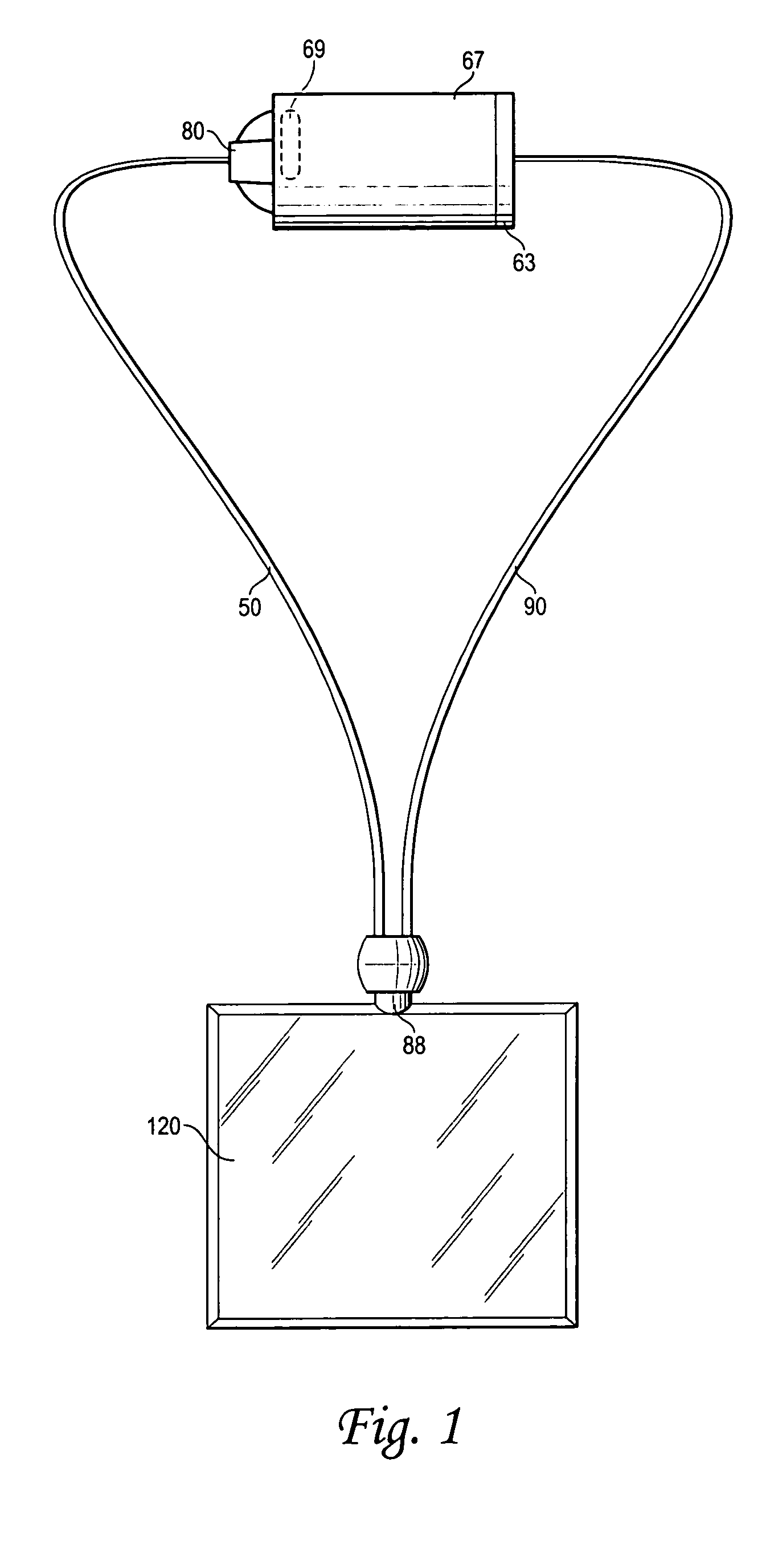
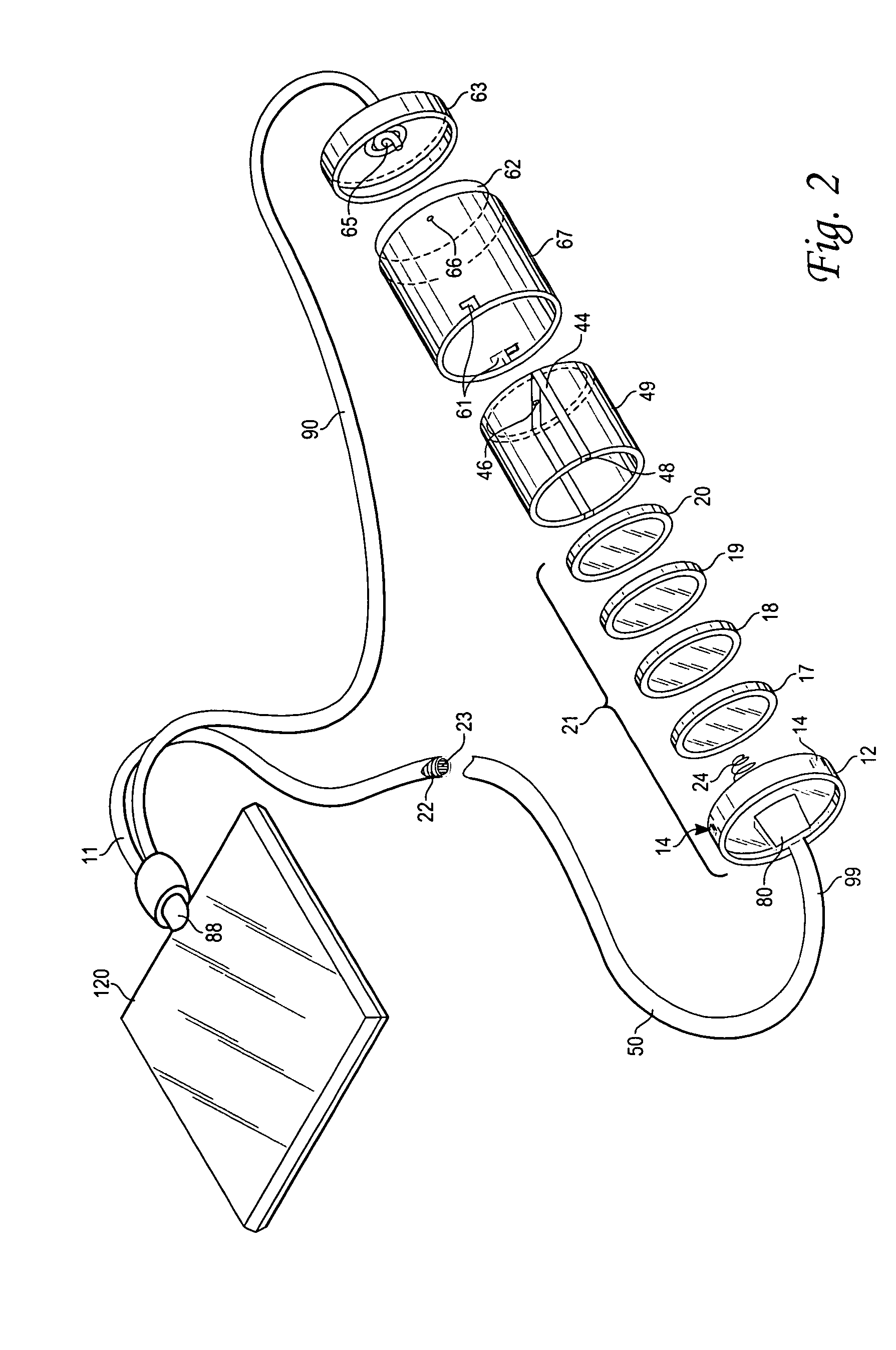
[0007]11 Bottom End[0008]12 Lid[0009]14 Square Steps[0010]21 Battery[0011]22 First Electrical Cord[0012]23 Second Electrical Cord[0013]24 Spring[0014]44 Metal Clip[0015]46 Dimpled Middle[0016]48 Top Battery Cage Rim[0017]49 Battery Cage[0018]50 First Strand[0019]61 L Shaped Slot(s)[0020]62 Barrel Housing Connector[0021]63 Second Strand Connector[0022]65 Knot[0023]66 Pinhole[0024]67 Barrel Shaped Battery Camber[0025]69 Mini Printed Circuit Board[0026]80 Button[0027]88 Light Emitting Diode[0028]90 Second Strand[0029]99 Top End[0030]120 Plastic Transparent Pendant

DESCRIPTION OF THE PREFERRED EMBODIMENT

[0031]The present invention is a lighted necklace with pendant. FIG. 1.

[0032]The pendant is formed as a light emitting diode 88 fixed on a plastic transparent pendant 120. The plastic transparent part 120 is preferably formed as a planar rectangular shape although other shapes and forms are easily prepared and manufactured through injection molding. The surface is preferably flat allowing...


PUM


Abstract

An LED illuminated pendant comprises a necklace formed of strands having a pair of electrical wires of positive and negative polarity. A barrel housing, a printed circuit board and a pendant lit by an LED element are mounted on the pendant. The strand joins to the barrel housing, and the barrel housing forms a housing connector at its end. The barrel houses a battery cage. The battery cage holds a plurality of batteries and electrical wires disposed within the first strand.

Description

DISCUSSION OF RELATED ART[0001]Illuminated jewelry has been disclosed as early as in U.S. Pat. No. Des. 251,629; U.S. Pat. Nos. 3,450,872; 3,689,758; and 4,101,955. Since then, a wide variety of illuminated necklaces have been invented and introduced into the marketplace. An illuminated necklace pendant is described by Murphy U.S. Pat. No. 4,262,324 and Kamara U.S. Pat. No. 6,601,965 including a battery held in a clasp held behind a neck of a user.[0002]The battery is commonly stored behind the neck in the battery case. Ohlund U.S. Pat. No. 6,122,933 shows a light emitting diode powered upon insertion of conductive wire into the battery chamber. Unfortunately, the separation of the circuit around a person's neck makes the construction cumbersome and overly complicated.[0003]Ohlund U.S. Pat. No. 5,477,433 provides intermittent illumination by intermittent electrical connection between the plurality of interlocking separate chain elements comprising the illuminated necklace. Other ill...

Claims


Application Information

Patent Timeline
Patent Type & Authority Patents(United States)
IPC IPC(8): A44C1/00A44C15/00
CPCA44C15/0015
Inventor CLEGG, TIM
Owner AMERICHIP
Why Eureka
Try Eureka