Microwave coupler

Inactive Publication Date: 2006-02-21
MICROLABFKR
View PDF15 Cites 9 Cited by
  • Summary
  • Abstract
  • Description
  • Claims
  • Application Information

AI Technical Summary

Benefits of technology

[0012]The present invention relates to TEM mode stripline directional couplers for coupling energy over a broad frequency range from a primary transmission line to a secondary transmission line with low loss and/or high directivity.
[0013]The present invention describes a method of extending the frequency bandwidth and power handling capacity of TEM mode thick strip line directional couplers by means of novel transmission line structures. In an exemplary embodiment, metallization is provided on three surfaces of a dielectric substrate having a rectangular cross-section. The arrangement of conductive surfaces on three sides of the dielectric substrate increases the effective conductor cross-section area as compared to the single layer metal conductor of a standard stripline component, thereby re

Problems solved by technology

While it has been possible to construct TEM mode couplers operating over wide frequency ranges using stripline techniques on solid dielectrics (where the dielectric constant, also known as dielectric permeability, Er>>1), it has been most difficult to do so using thick conductors in air dielectric (Er=1).
The inherent size of the transmission lines in air has limited usage of these components to narrow bandwidths.
Known TEM mode components suffer from degradation due to non-TEM propagation, manifesting itself as resonance in the pass band of the coupler.
Low power components can use microwave absorbers

Method used


Image

  • Microwave coupler
  • Microwave coupler
  • Microwave coupler

Examples


Example

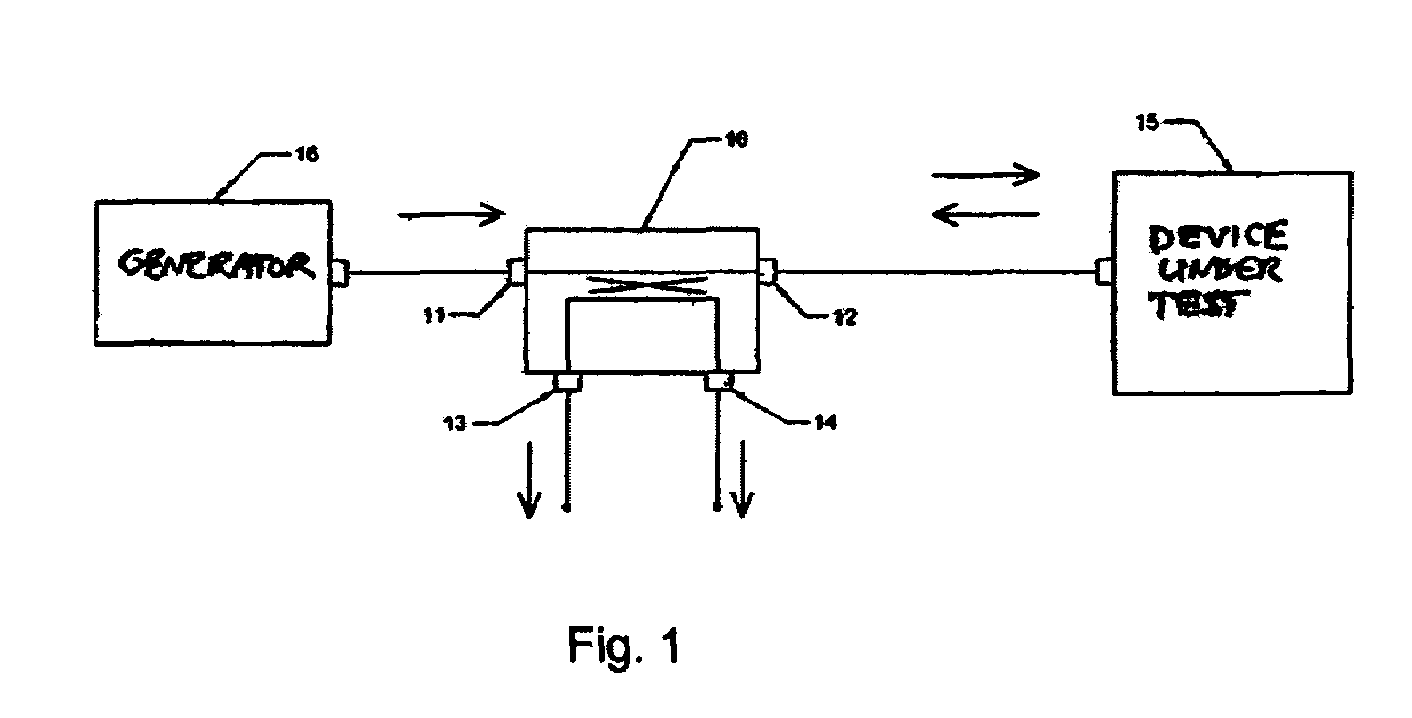
[0021]FIG. 1 shows an exemplary directional coupler 10 used in a typical application. In the application illustrated, the coupler 10 is used in a test setup to monitor the signal levels of forward and reflected power for a device under test 15. The coupler 10 comprises an input port 11 which is coupled to the output of an RF generator 16 and an output port 12 which is coupled to the device under test 15. The coupler 10 provides at a first coupled output port 13 a signal which is a predetermined fraction of the forward signal flowing from the RF generator 16 to the device under test 15. The coupler also provides at a second coupled output port 14 a signal which is a predetermined fraction of any reflected signal flowing back from the device under test 15 to the RF generator 16. Ideally, none of the reflected power appears at the first coupled output port 13 and none of the forward power appears at the second coupled output port 14.

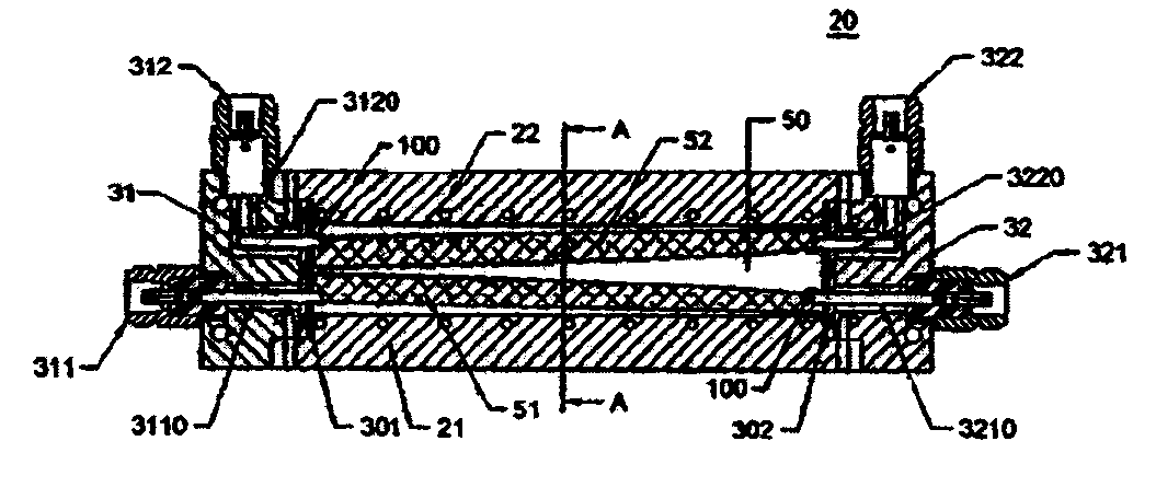
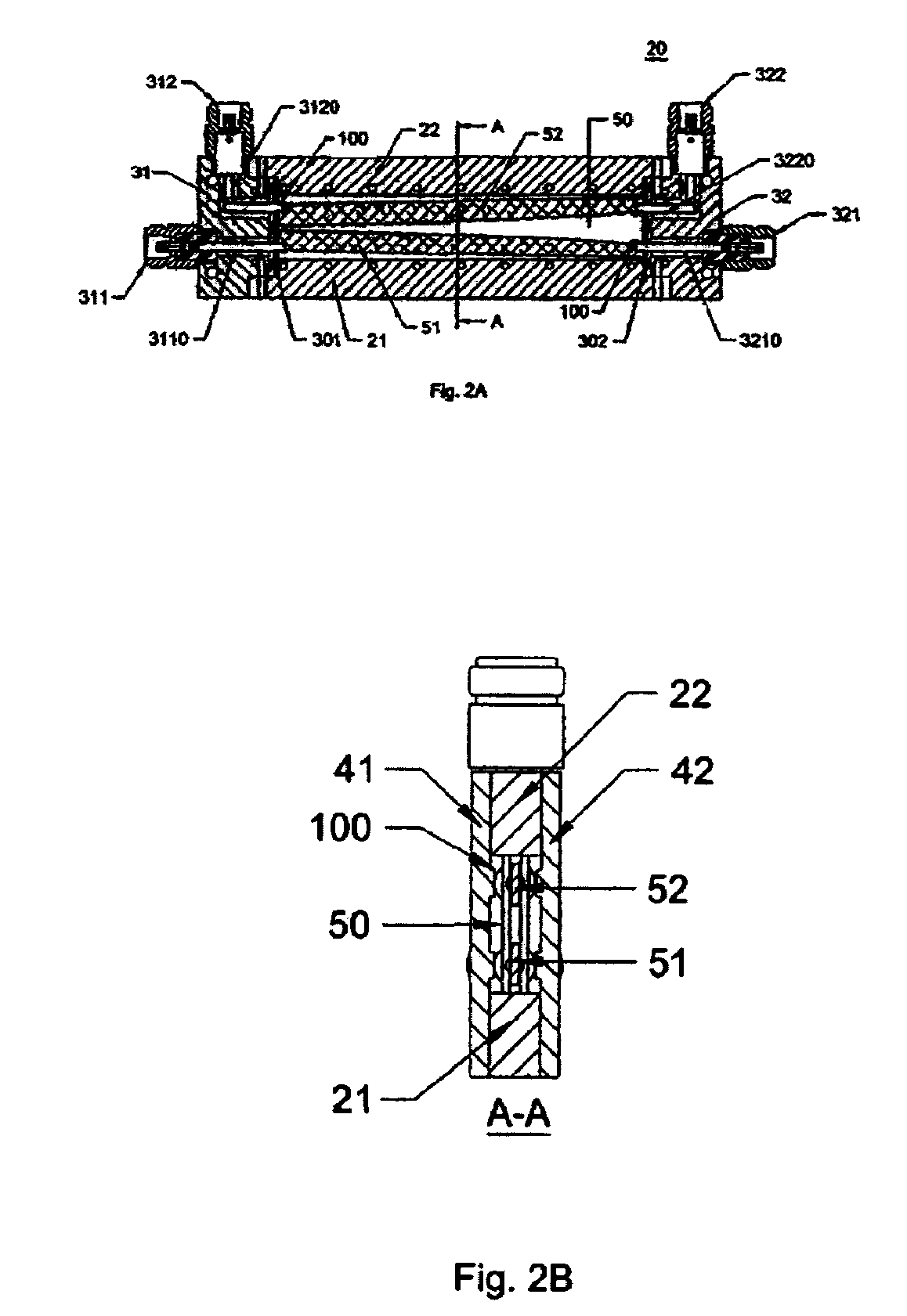
[0022]FIG. 2A is a plan view of a first exemplary emb...


PUM


Abstract

A high power, TEM mode directional microwave coupler having low loss and expanded bandwidth uses novel thick suspended substrate conductors to provide multi-octave bandwidth performance in a practical package. Each of two center conductors is formed using metal layer deposited onto three surfaces of a thick dielectric substrate. The conductors, which can be edge-coupled or offset-coupled, form a novel structure in which the non-metallized side of the substrate is oriented toward the facing outside vertical walls. This effectively reduces the effect of the package wall on the coupling structure, permitting a smaller, constant-width dimension, which in turn raises the waveguide cut-off frequency. The result is a directional coupler with an extended high frequency performance, with reduced physical size and low loss.

Description

FIELD OF THE INVENTION[0001]The present invention relates to microwave devices, particularly to transverse electro-magnetic (TEM) mode stripline directional couplers and to methods of making same.BACKGROUND INFORMATION[0002]The term “directional coupler” refers in general to a four-port passive microwave device, where a main line conductor (also called the “through” line) carries RF power. The main line conductor is in close proximity and is coupled to a secondary conductor by the electromagnetic field generated by the RF signal. The RF current flowing forward through the main line will induce RF current flow in the coupled conductor flowing in the opposite direction, and will only appear at one of the coupled ports (i.e., a signal current flowing from left to right on the main line will induce a signal current flowing from right to left in the coupled conductor and appear only from the left coupled output). As a result, the coupled output of forward and reverse flow of RF current w...

Claims


Application Information

Patent Timeline
IPC IPC(8): H01P5/18
CPCH01P5/185H01P5/18
Inventor ANTKOWIAK, MAREK E.SAWICKI, ANDRZEJ
Owner MICROLABFKR
Why Eureka
Try Eureka