

Signal dividing device
- Summary
- Abstract
- Description
- Claims
- Application Information
AI Technical Summary
Benefits of technology
Problems solved by technology
Method used
Image

Examples
Embodiment Construction
[0014]Existing in-home coaxial networks often use signal dividers to split a television (TV) signal from an external service provider into a number of identical signals accessible by multiple items of consumer equipment connected to the in-home network. The signal dividers have a good return loss on their input and output ports and high isolation between their output ports. This ensures television signals transmitted to the in-home network do not suffer unduly from signal noise but two-way communication using the signal divider is very difficult and in many cases even impossible. Thus, other technologies, such as PowerLine, MoCA, and wireless, are difficult to use in combination with the existing coaxial network. The high isolation between the output ports of the signal divider provides a high signal path loss between the different outlets in the home.
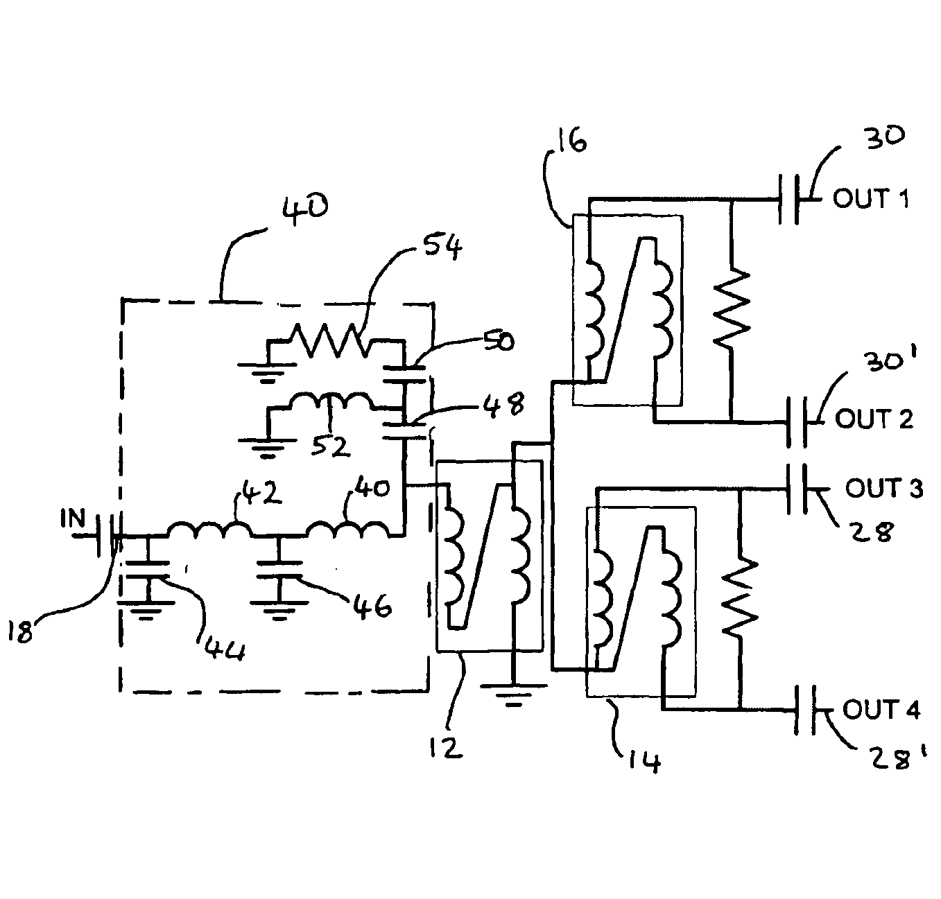
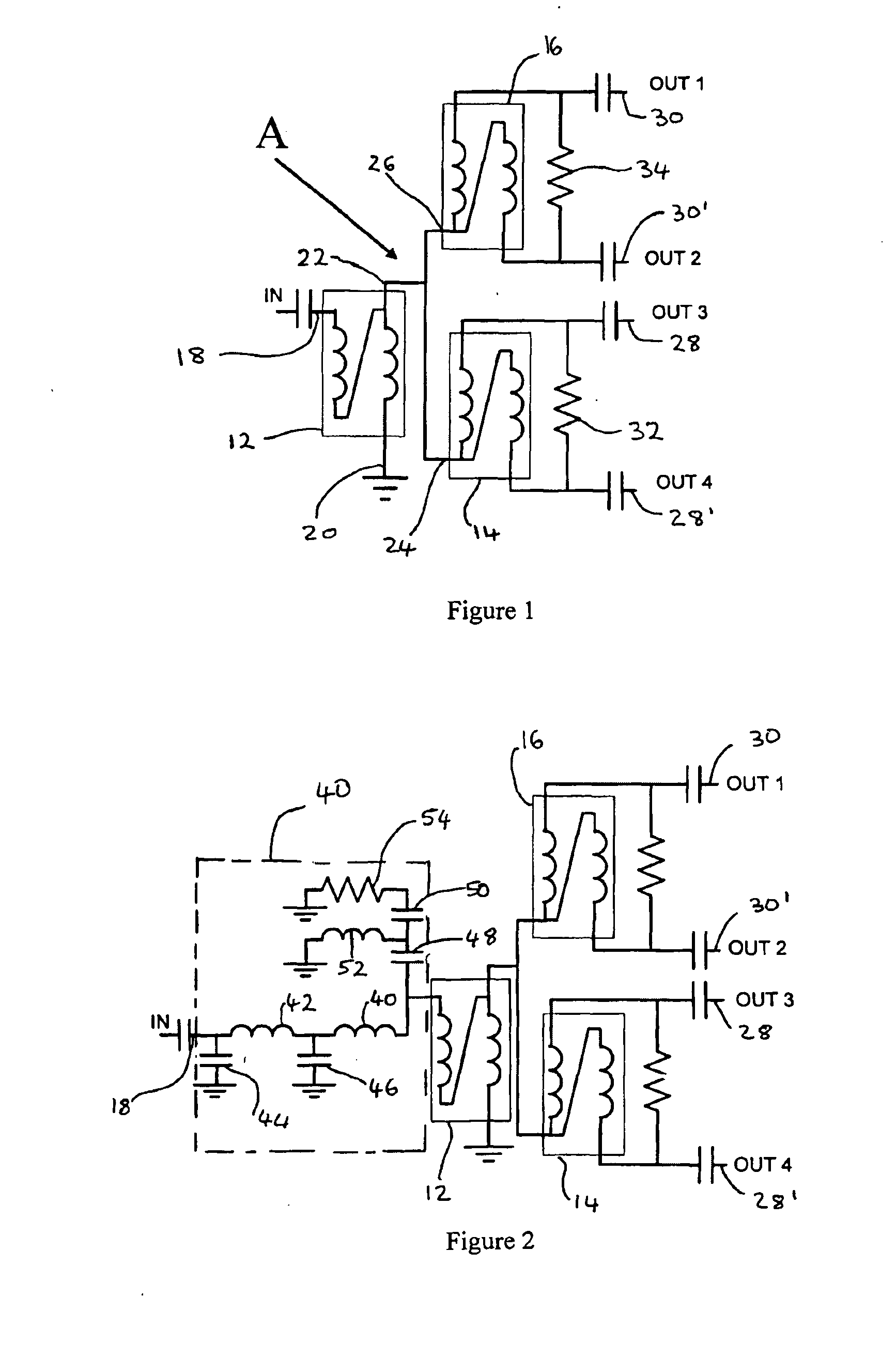
[0015]FIG. 1 shows a signal dividing device in accordance with the present invention that allows two-way communication of TV, data an...
PUM
 Abstract
Description
Claims
Application Information