Thin film magnetic head and method of manufacturing same

a thin film, magnetic head technology, applied in the construction of head windings, instruments, data recording, etc., can solve the problems of difficult to precisely control the track pb>2, difficult to form the top pole in a desired shape, and difficult so as to reduce the thickness of the photoresist film on the top and bottom of the apex area. , the effect o

Inactive Publication Date: 2006-02-21
TDK CORPARATION
View PDF18 Cites 5 Cited by
  • Summary
  • Abstract
  • Description
  • Claims
  • Application Information

AI Technical Summary

Benefits of technology

[0040]In the thin film magnetic head of the invention, as part of the thin film coil faces either of two facing poles through an insulating layer, a magnetomotive force from the thin film coil can be conducted to a facing pole efficiently.
[0044]Further, by burying the thin film coil within the concave region adjacent to the first magnetic pole, the difference in height in the apex area can be decreased compared to that of the related art. As a result, in the following process, when forming a second magnetic layer by photolithography, the difference in thickness of the photoresist film on the top and the bottom of the apex area is reduced. Accordingly, the second magnetic layer of the submicron measurement can be formed.
[0045]In addition, in the other thin film magnetic head of the invention, a thin film coil is not necessary to be formed away from the throat height zero position. As a result, the thin film coil can be formed in the vicinity of the throat height zero position of the end of the first magnetic pole. Also, since a second magnetic pole faces to a part of the first magnetic pole and the thin film coil sandwiching the write gap layer, the magnetomotive force from the thin film coil can be conducted to the second magnetic pole efficiently.
[0047]First, in a thin film magnetic head and a method of manufacturing the same according to the invention, the length from a surface of the first magnetic pole facing the recording medium may be formed to be equal to the throat height of the recording head. That is, in the thin film magnetic head and the method of manufacturing the same according to the invention, as the first magnetic pole is divided from the first magnetic layer and formed to be protruded shape against the first magnetic layer, an insulating layer made of an inorganic material is formed adjacent to the first magnetic pole. As a result, the throat height can be determined precisely by making the length of the first magnetic pole from the surface facing the recording medium to the inner direction equal to the length of the throat height of the recording head.

Problems solved by technology

Accordingly, it is necessary to form a micro pattern with submicron width with a photoresist film of equal to or more than 8 to 10 μm in thickness, however, it has been extremely difficult.
As a result, the top pole can not be formed in a desired shape because side walls of the top pole take a rounded shape and so on.
As described, with a related art, it has been extremely difficult to precisely control the track P2W and to precisely form the top pole so as to have a narrow track structure.
Therefore, the throat height, which is required to have a highly precise measurement, is not formed to be uniform.
As a result, the track width of the magnetoresistive element becomes unbalanced in a procedure of processing and polishing of the track surface.
As a result, the problem that writing of recording data cannot be performed has often occurred.(2) As described above, in the magnetic head of the related art, it is not necessary to process the top pole layer 116 as minute as the pole tip 110, because the track width of the recording head is determined by the pole tip 110 which is one of the top pole being divided into two.
However, it is difficult to perform fine-process of the top pole layer 116 since there is a significant difference in height as described above in the apex area under the top pole layer 116.(3) In the magnetic head of the related art, there is a problem that it is difficult to shorten a yoke length.
However, etching a seed layer for forming the second layer can not be performed in the slope of the apex area causing the coil to short-circuit, which makes it impossible to form the second layer of the coil.
Therefore, since 6–8 μm is required in the apex area of the outer peripheral end, shortening of the yoke length is impossible.
This has prevented the high frequency characteristics from improving.
However, in this technique, it is not possible to form a thin film coil in the vicinity of the throat height zero position and to conduct a magnetomotive force from a thin film coil to a pole efficiently.
Further, the problems described above, including precision control of the throat height at the recording head, can not be solved.
However, in this technique, it is not possible to conduct the magnetomotive force from a thin film coil to a pole efficiently, and the problems described above, including precision control of the throat height, can not be solved.

Method used


Image

  • Thin film magnetic head and method of manufacturing same
  • Thin film magnetic head and method of manufacturing same
  • Thin film magnetic head and method of manufacturing same

Examples


first embodiment

[First Embodiment]

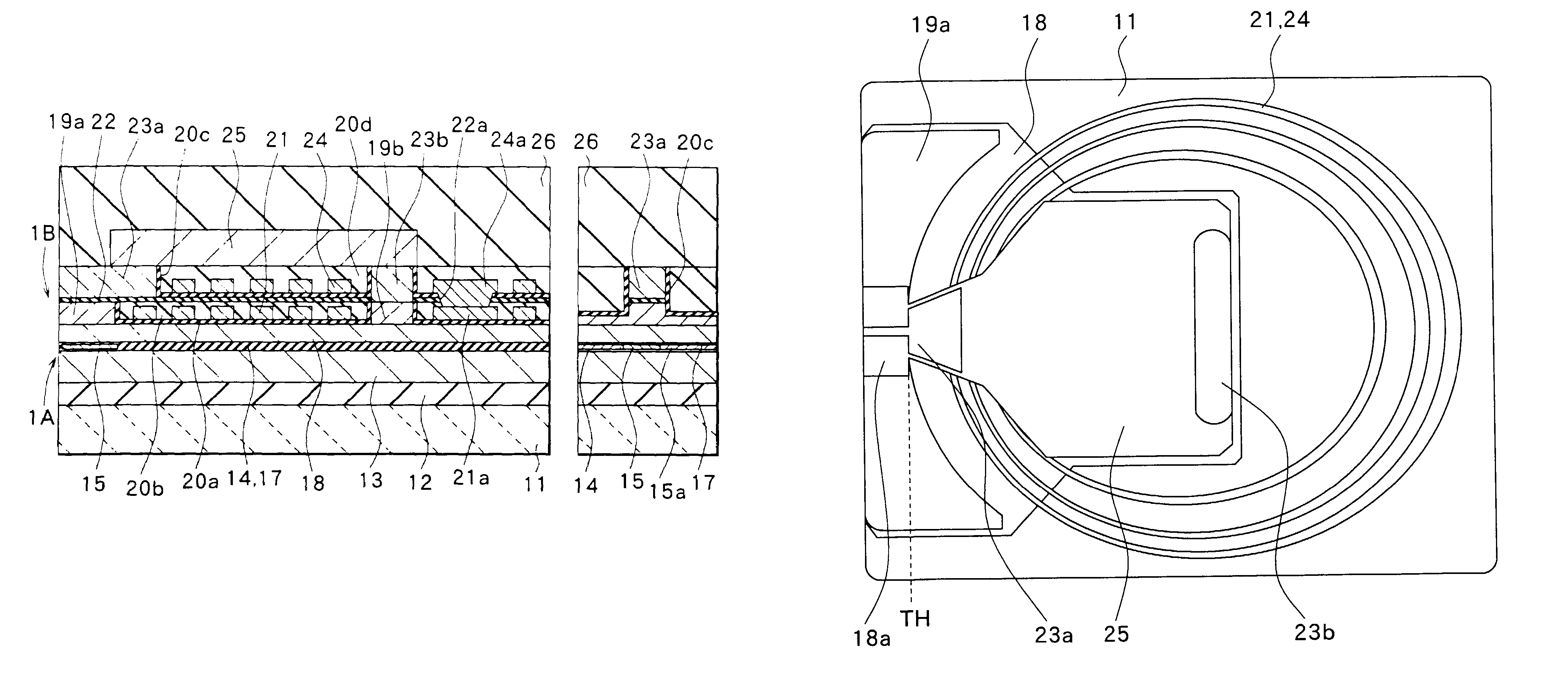
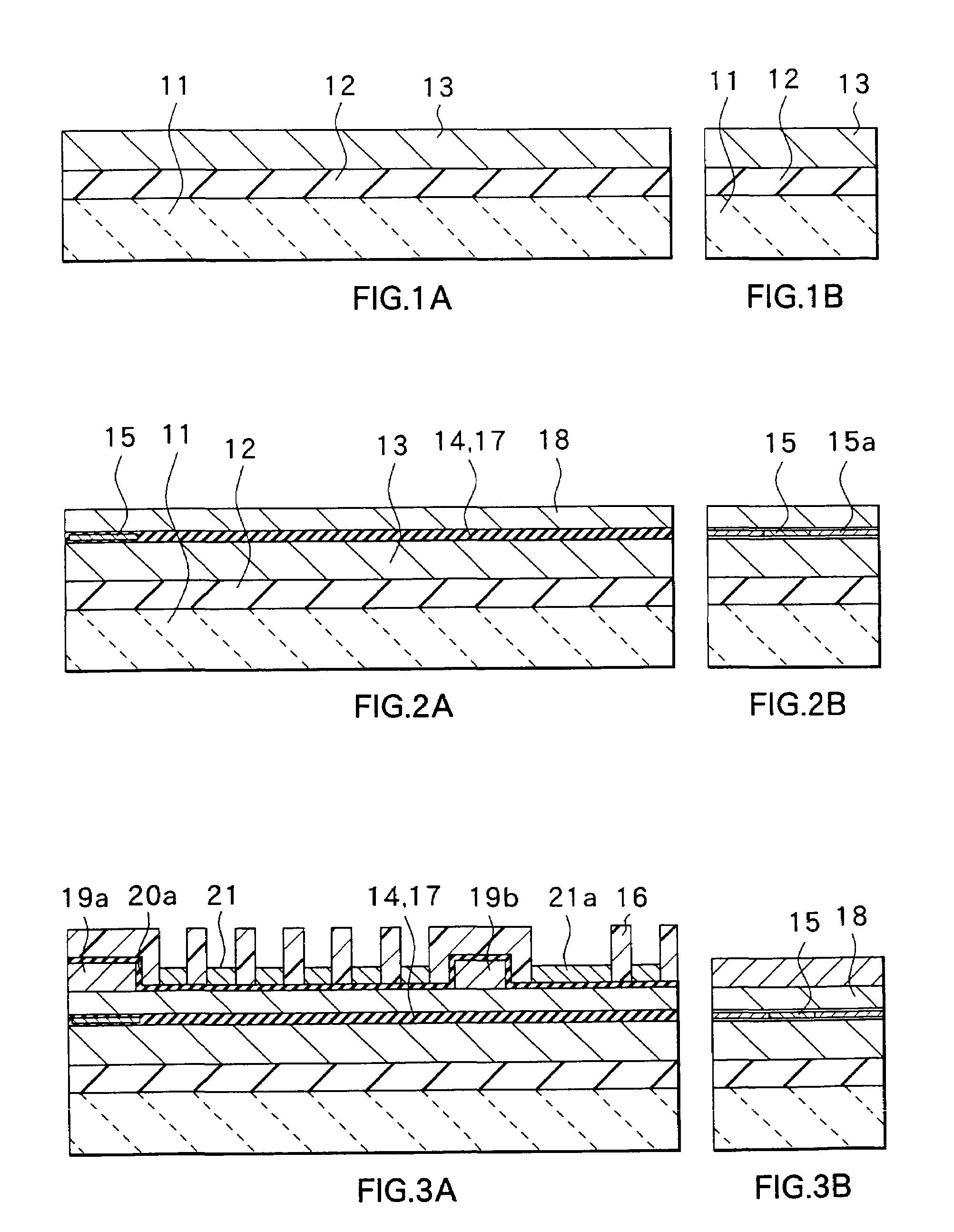
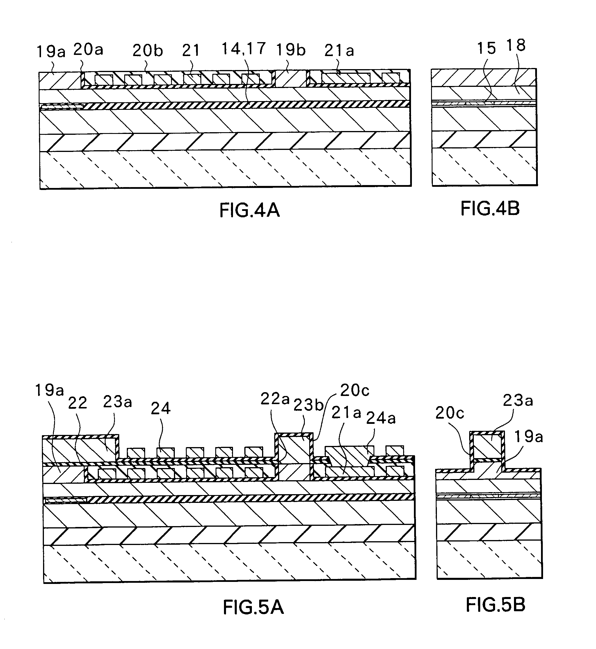
[0072]FIGS. 1A and 1B to FIGS. 6A and 6B illustrate a manufacturing process of a composite thin film magnetic head as a thin film magnetic head according to the first embodiment of the invention, respectively. FIGS. 1A–6A show the cross sections vertical to the track surface (ABS), and FIGS. 1B–6B show the cross sections parallel to the track surface of the magnetic pole portion.

[0073]First, the configuration of a composite thin film magnetic head according to the embodiment of the invention will be described with reference to FIGS. 6A and 6B. The magnetic head comprises a magnetoresistive reading-out head (called reproducing head in the followings) 1A for reproducing and an inductive recording head (called recording head in the followings) 1B for recording.

[0074]The reproducing head 1A is a pattern of magnetoresistive film (called MR film in the followings) 15 being formed on a substrate 11 made of, for example, altic (Al2O3.TiC) through an insulating layer 12 for...


PUM

PropertyMeasurementUnit
thicknessaaaaaaaaaa
thicknessaaaaaaaaaa
thicknessaaaaaaaaaa

Abstract

A bottom pole is divided into a bottom pole tip and a bottom pole layer. The bottom pole tip is formed on a flat surface of the bottom pole layer, and insulating layers made of inorganic materials are buried in a concave part between the bottom pole tip and a bottom connecting portion. The throat height is determined by the end close to the bottom pole tip of the insulating layer. An top pole tip is formed to be longer than the bottom pole tip on a write gap layer and is extended to a position facing part of a thin film coil. Magnetomotive force from the thin film coil is conducted to the top pole tip efficiently, and a write characteristic of a thin film magnetic head is improved.

Description

[0001]This application is a divisional of application Ser. No. 09 / 455,319 filed Dec. 6, 1999, issued as U.S. Pat. No. 6,483,665. The entire disclosure of the prior application is hereby incorporated by reference herein in its entirety.BACKGROUND OF THE INVENTION[0002]1. Field of the Invention[0003]The present invention relates to a thin film magnetic head having at least an inductive-type magnetic transducer for writing and a method of manufacturing the same.[0004]2. Description of the Related Art[0005]In recent years, performance improvement in thin film magnetic heads has been sought in accordance with an increase in surface recording density of a hard disk drive. A composite thin film magnetic head, which is made of a layered structure having a recording head with an inductive-type magnetic transducer for writing and a reproducing head with a magneto resistive element (referred to as MR element in the followings) for reading-out has been widely used as a thin film magnetic head. ...

Claims


Application Information

Patent Timeline
Patent Type & Authority Patents(United States)
IPC IPC(8): G11B5/147G11B5/31G11B5/39
CPCG11B5/313G11B5/3116G11B5/3967
Inventor SASAKI, YOSHITAKA
Owner TDK CORPARATION
Why Eureka
Try Eureka