
Supportive device for handicapped people

a technology for supporting devices and handicapped people, which is applied in the direction of wheelchairs/patient conveyances, transportation and packaging, and bedsofas. it can solve the problems of difficult to control the patient's weight, unstable patient, and uncomfortable feelings of the patient and the toil and time experienced by the helper

Inactive Publication Date: 2006-02-28
IURA CO LTD
View PDF15 Cites 36 Cited by
  • Summary
  • Abstract
  • Description
  • Claims
  • Application Information

AI Technical Summary

Benefits of technology

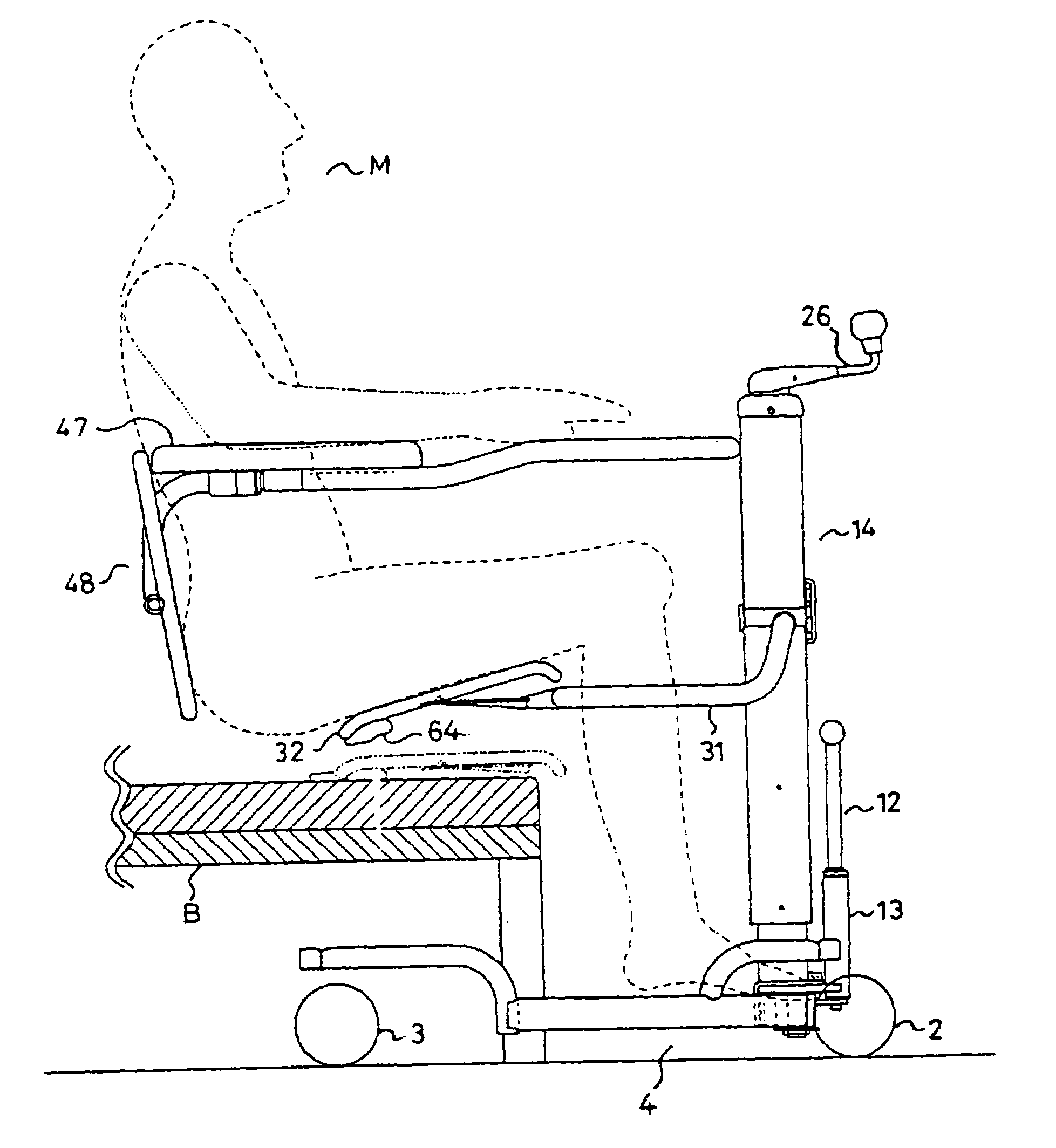
[0010]Preferably, a bag filled with air or gas or liquid is placed behind the thigh supports, the bag being elastically expanded behind the thigh supports when the lowering thigh supports come into contact with a target structure such as a bed, thereby avoiding the risk that the patients are subjected to strong shock and be pinched in their thighs.
[0013]It is also preferred that the rotary bearing is inclined rearward, so that the patient can shift smoothly with his or her knees keeping out of collision or contact with the rotary bearing.
[0015]It is also preferred that a pair of front wheels are provided on the undersurface of a footrest, so that the patients are protected from their feet and fingers being pinched.
[0020]It is desired that to prevent slipping-off trouble, the back upholstery is provided with a belt.
[0026](d) The lifting device of the thigh supports is operated to adjust a height of the thigh supports, and causes the thigh supports to rotate from their upper position to their lower position and insert into a triangular space formed between the patient's thighs and the bed along the patient's thighs;

Problems solved by technology

This type of supportive device is known, but a major disadvantage is the uncomfortable feelings felt by the patient and the toil and time experienced by helpers when he or she has to be suspended by a belt or the like.
These two known devices employ a pedal for operating the pillar and column but in operating them the patient feels unstable because of frequent unexpected movements.
In addition, it is difficult to control the patient's weight when he or she is shifted one structure to other.
Especially when the helpers are powerless such as women or aged people, the known supportive devices are difficult to operate.
The patient has to lean his or her upper body against the receiving plate or the body holder but in this position it is difficult to change their angle of inclination, height, and position.
This is very inconvenient.

Method used


Image

  • Supportive device for handicapped people
  • Supportive device for handicapped people
  • Supportive device for handicapped people

Examples


Embodiment Construction

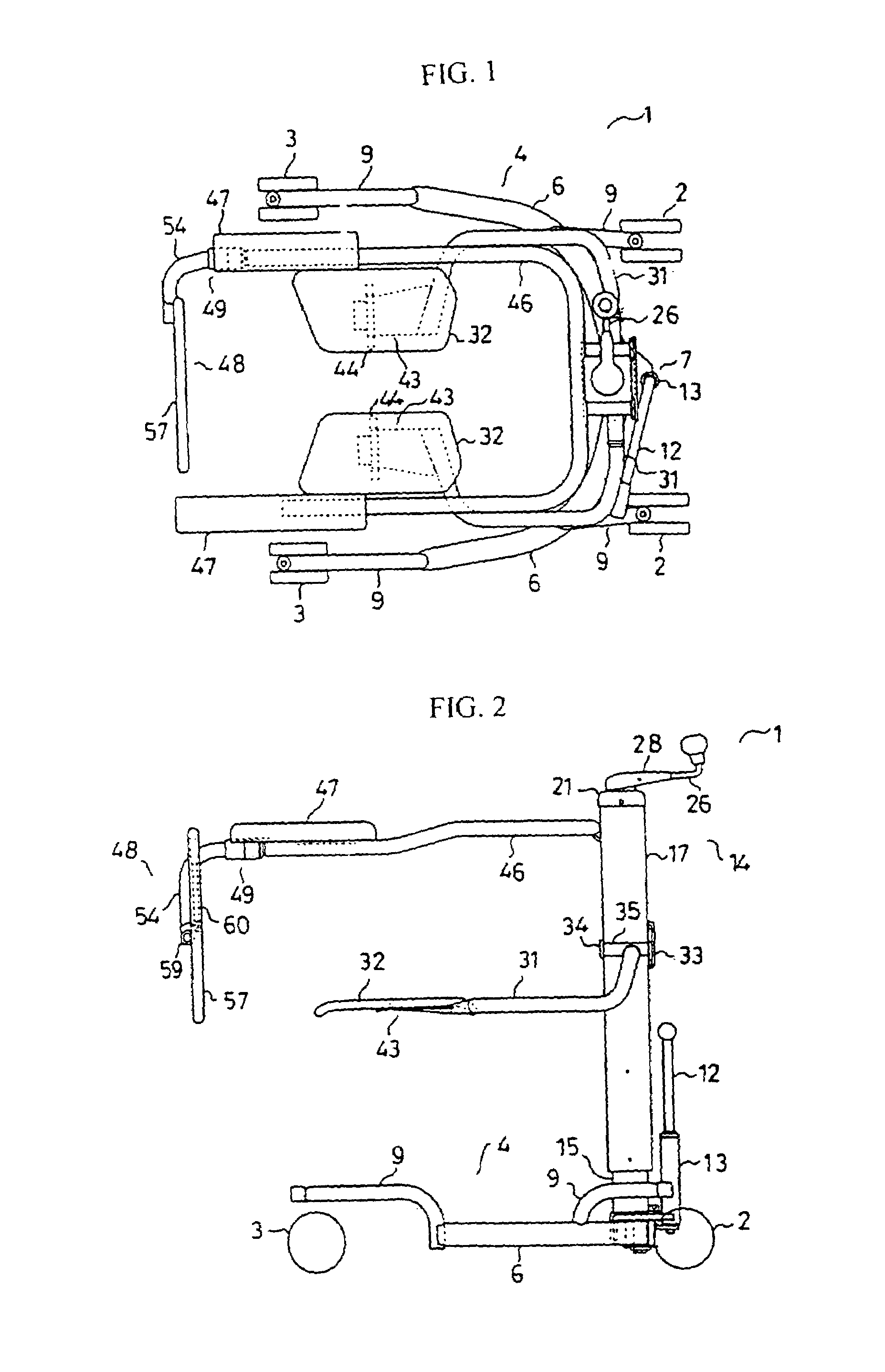
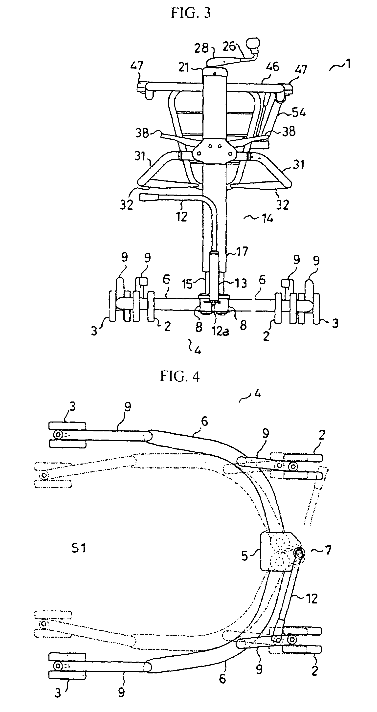
[0067]The illustrated supportive device 1 includes a chassis 4 having a pair of front wheels 2 and a pair of rear wheels 3. As best shown in FIG. 4, the chassis 4 is constituted by a base 5 and arms 6 extending rearward with a space S1 therebetween which opens rearwards. An expanding device (hereinafter ‘expander’) 7 is optionally provided in the chassis 4 whereby the arms 6 are expanded or contracted to adjust the width of the chassis 4.

[0068]The base 5 is L-shaped, and is provided with a pair of shafts 5a which rotatably carry bearings 8 coupled to the ends of supports 6. The supports 6 are slightly curved in the form of Letter L in its plan view, and provided with L-shaped caster supports 9 at its front and rear ends. The bearings 8 include a groove in which a key 10 fits, thereby effecting a unitary rotation of the bearings 8 in accordance with the rotation of either of them. One of the bearings 8 is provided with a plate 11 projecting forward. The plate 11 is provided with a ho...


PUM


Abstract

A moving device (1) capable of being operated easily and safely to move a person between various types of beds and chairs by supporting the femoral region and backbone of a person to be moved instead of by suspending the person to be moved by a belt or supporting the axillas and knees of the person, comprising a body frame (4) having a pair of right and left front wheels (2) and rear wheels (3) and having an open rear side, a column (14) erected on the body frame, a pair of right and left side seat parts (32) provided on a pair of right and left side arms (31) fixed to the column, a handrail frame body (46) fixed to the column and having an open rear side, a backbone supporting part (48) disposed at the rear of the seat parts, and a lifting mechanism capable of lifting the seat parts vertically, wherein the arms are formed in a crank-shape and connected pivotally to the column through longitudinal shafts positioned at the front of the knees of the person to be moved, and the seat parts are rotated eccentrically from the outside upper side to the inside lower side so as to insert the seat parts into the lower side of the femoral region while bypassing the knee parts of the person to be moved.

Description

FIELD OF THE INVENTION[0001]The present invention relates to a supportive device for helping handicapped people including the invalid who cannot look after themselves because of illness, old age, or injury (hereinafter, referred to as ‘patient’ or ‘patients’), and more particularly to such a supportive device which easily and safely helps patients shift from one structure such as a bed to other such as a supportive wheeled chair (hereinafter ‘supportive chair’), a toilet, a shower chair, and a sofa, and vice versa, wherein they can continue to stay on the original structure such as a bed and are not required to stand up therefrom.BACKGROUND ART[0002]This type of supportive device is known, but a major disadvantage is the uncomfortable feelings felt by the patient and the toil and time experienced by helpers when he or she has to be suspended by a belt or the like. To solve this problem, various solutions are proposed; one example is disclosed in Japanese Patent Laid-Open Application...

Claims


Application Information

Patent Timeline
IPC IPC(8): A61G7/10A61G5/10A61G5/12A61G7/14
CPCA61G7/053A61G7/1019A61G7/1046A61G7/1051A61G7/1067A61G7/1088A61G7/1092A61G7/1098A61G5/1059A61G2200/34A61G2005/125A61G2005/128A61G7/1069A61G5/125A61G5/128A61G7/1096
Inventor IURA, TADASHITSUKAMURA, YOSHIYUKIYAMAMOTO, KEIJI
Owner IURA CO LTD
Learn More