Template for fitting exit hardware on a door

Inactive Publication Date: 2006-02-28
LUCIANI MICHAEL
View PDF29 Cites 37 Cited by
  • Summary
  • Abstract
  • Description
  • Claims
  • Application Information

AI Technical Summary

Benefits of technology

[0025]A further objective is to provide a template for cutting a door that is

Problems solved by technology

The wide variety of possible preparations has prevented the development of a more advanced

Method used


Image

  • Template for fitting exit hardware on a door
  • Template for fitting exit hardware on a door
  • Template for fitting exit hardware on a door

Examples


Embodiment Construction

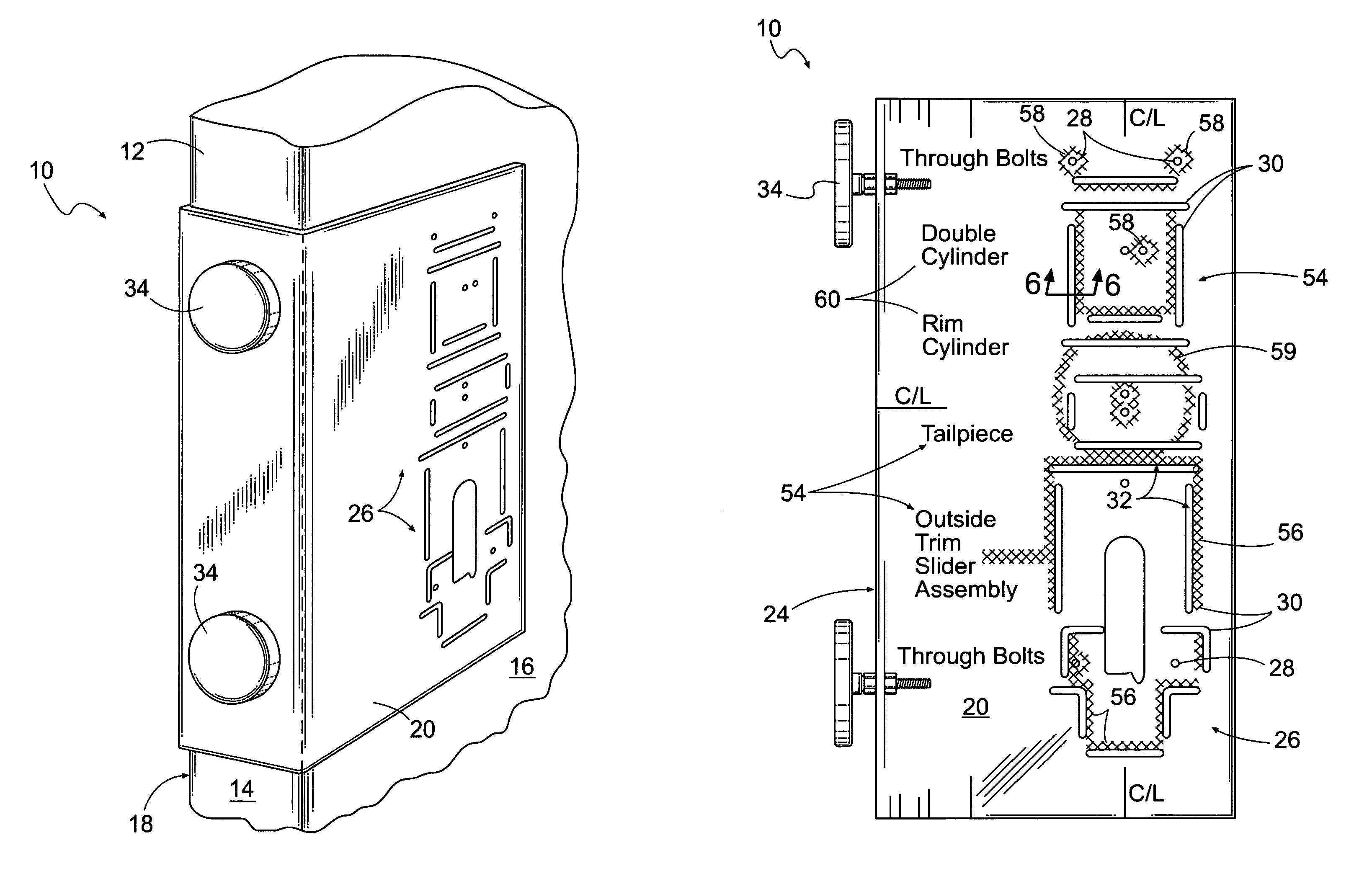
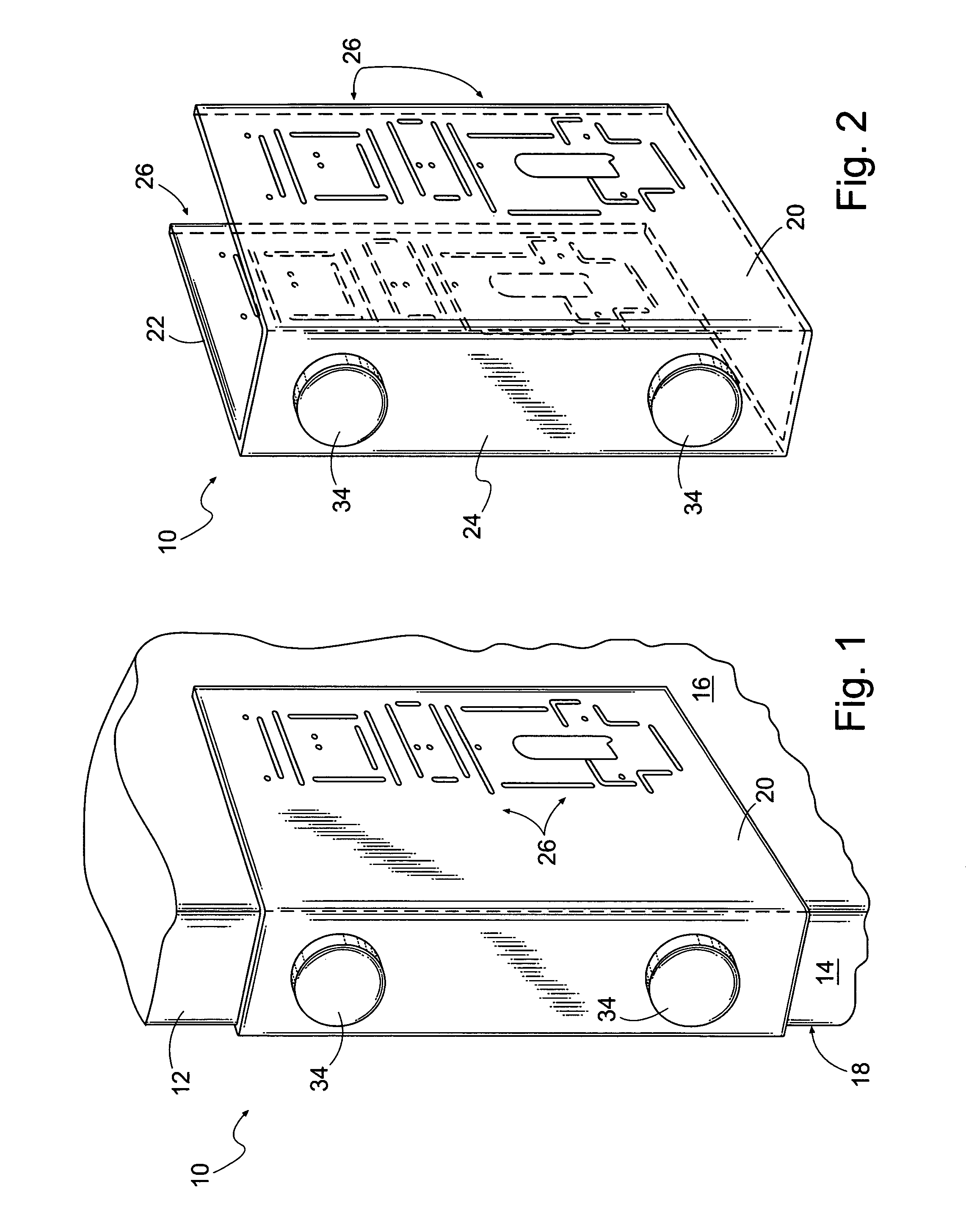
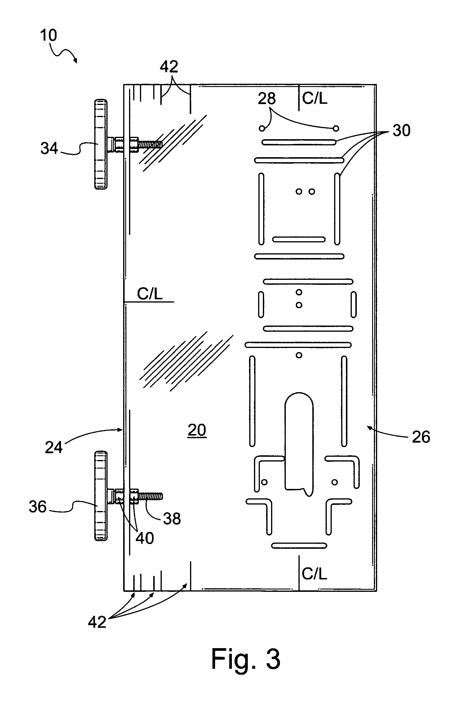
[0036]FIG. 1 illustrates a template 10 for preparing a door 12 for the mounting of various types of exit hardware (not shown). The template 10 includes a plurality of apertures and slots 26 for indicating where the cuts should be made and holes drilled, once the template 10 has been mounted upon the door 12, as shown and as described below. The door 12 has an edge 14, a front face 16, and a rear face 18. The door 12 is prepared by various cutting and drilling actions to accept the various types of exit hardware.

[0037]FIG. 2 is a perspective view of the template 10, illustrating first, second, and third sidewalls 20, 22 and 24 of the template 10. The first sidewall 20 and the second sidewall 22 are supported in generally parallel planes by the third sidewall 24. For purposes of this disclosure, the term “generally parallel planes” shall mean only that the first sidewall 20 and the second sidewall 22 are supported to operatively abut or engage the front face 16 and the rear face 18, r...


PUM


Abstract

A template for cutting a door has a first sidewall having a plurality of through holes through the first sidewall indicating centers of proposed mounting holes, and a plurality of through slots, each having first and second edges separated by a width. Both the first and second edges indicate proposed cutting lines with the width operably spacing the first and second edges. First and second indicia printed on the first sidewall for indicating the through holes and the edges that together operate to indicate the holes and cuts necessary for first and second cutting operations, respectively.

Description

CROSS-REFERENCE TO RELATED APPLICATIONS[0001]This application for a utility patent claims the benefit of U.S. Provisional Application No. 60 / 487,165, filed Jul. 14, 2003. The previous application is hereby incorporated by reference in its entirety.STATEMENT REGARDING FEDERALLY SPONSORED RESEARCH[0002]Not ApplicableBACKGROUND OF THE INVENTION[0003]The preparation of commercial wood doors for hardware is a specialized part of the door industry. The specialization comes from the great variety of hardware that can be used. For example, the preparation of a door for the attachment of exit devices may require a wide variety of preparations depending upon the specific type of exit device being installed. Previously, it has been necessary to use a specialized template that is unique to each exit device. The wide variety of possible preparations has prevented the development of a more advanced template, as the template could not be designed to handle more than one type of preparation.[0004]T...

Claims


Application Information

Patent Timeline
IPC IPC(8): G01B5/24G01B5/14
CPCE05B17/06B27F5/12
Inventor LUCIANI, MICHAEL
Owner LUCIANI MICHAEL
Why Eureka
Try Eureka