

Forage harvester with positionable operator's cabin
a positionable, operator-type technology, applied in the direction of mowers, harrows, etc., can solve the problems of increased total weight of the forage harvester, difficult control of roadway unevenness, and vehicles sensitively reacting to steering impacts and roadway unevenness
- Summary
- Abstract
- Description
- Claims
- Application Information
AI Technical Summary
Benefits of technology
Problems solved by technology
Method used
Image

Examples
Embodiment Construction
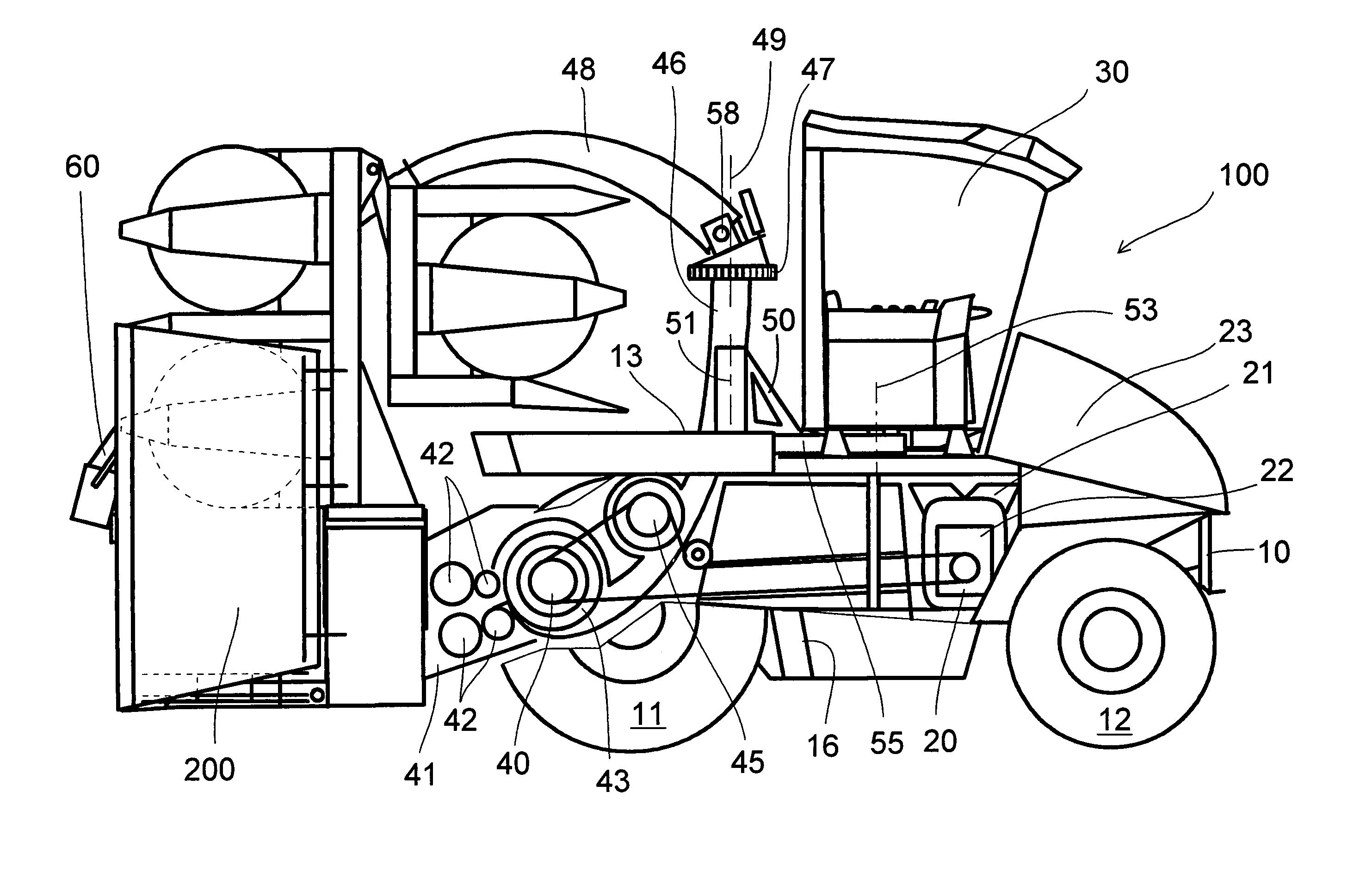
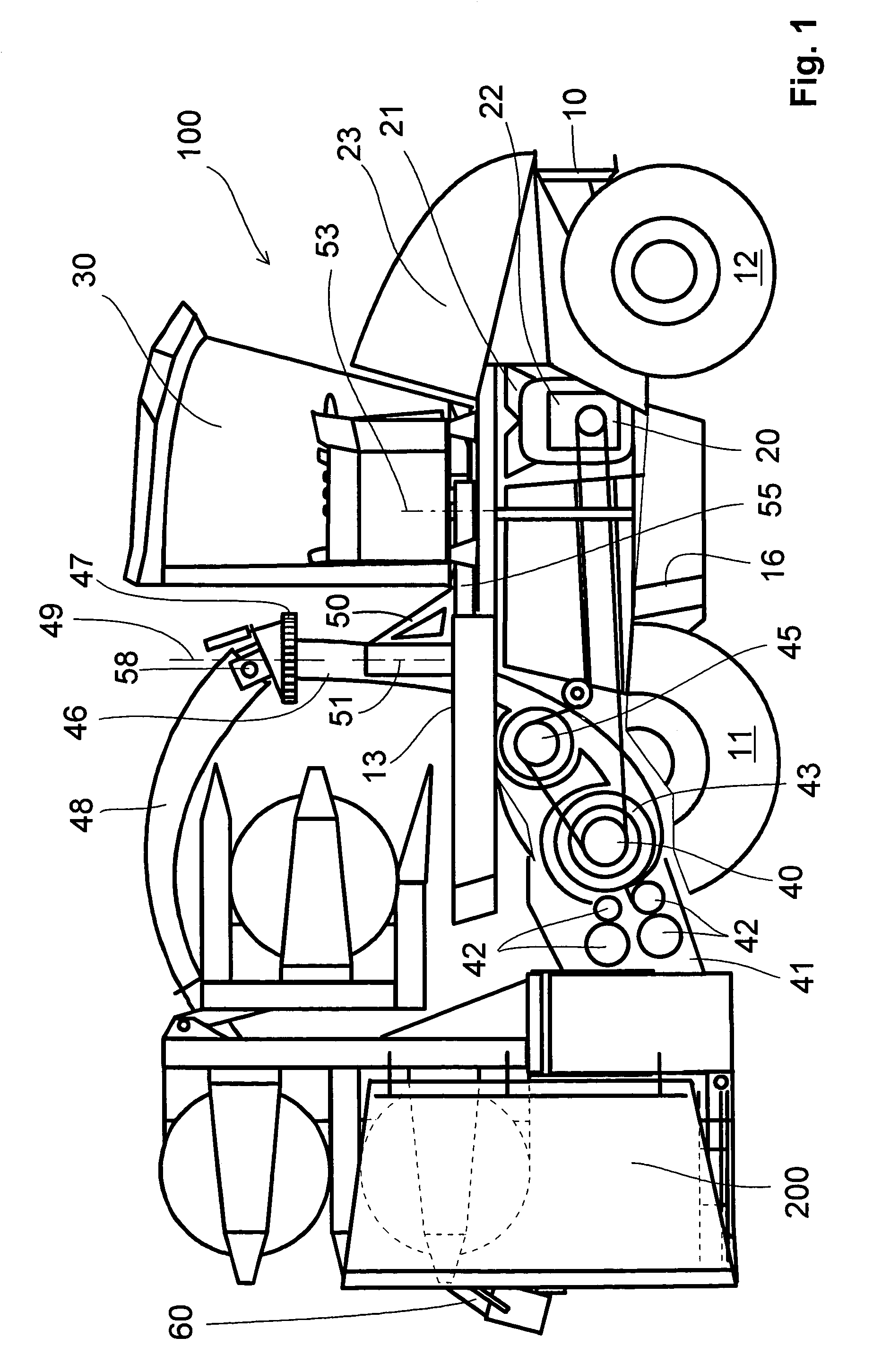
[0032]A forage harvester in FIG. 1 is identified as a whole with reference numeral 100. It has a chassis 10 and an operator's cabin 30 arranged on the chassis. In addition to the cabin 30, also an upper end of an ascending lower discharge chute 46 is arranged on the chassis 10. It extends from a chopper drum 43 inside the chassis 10 to a level above the chassis 10.
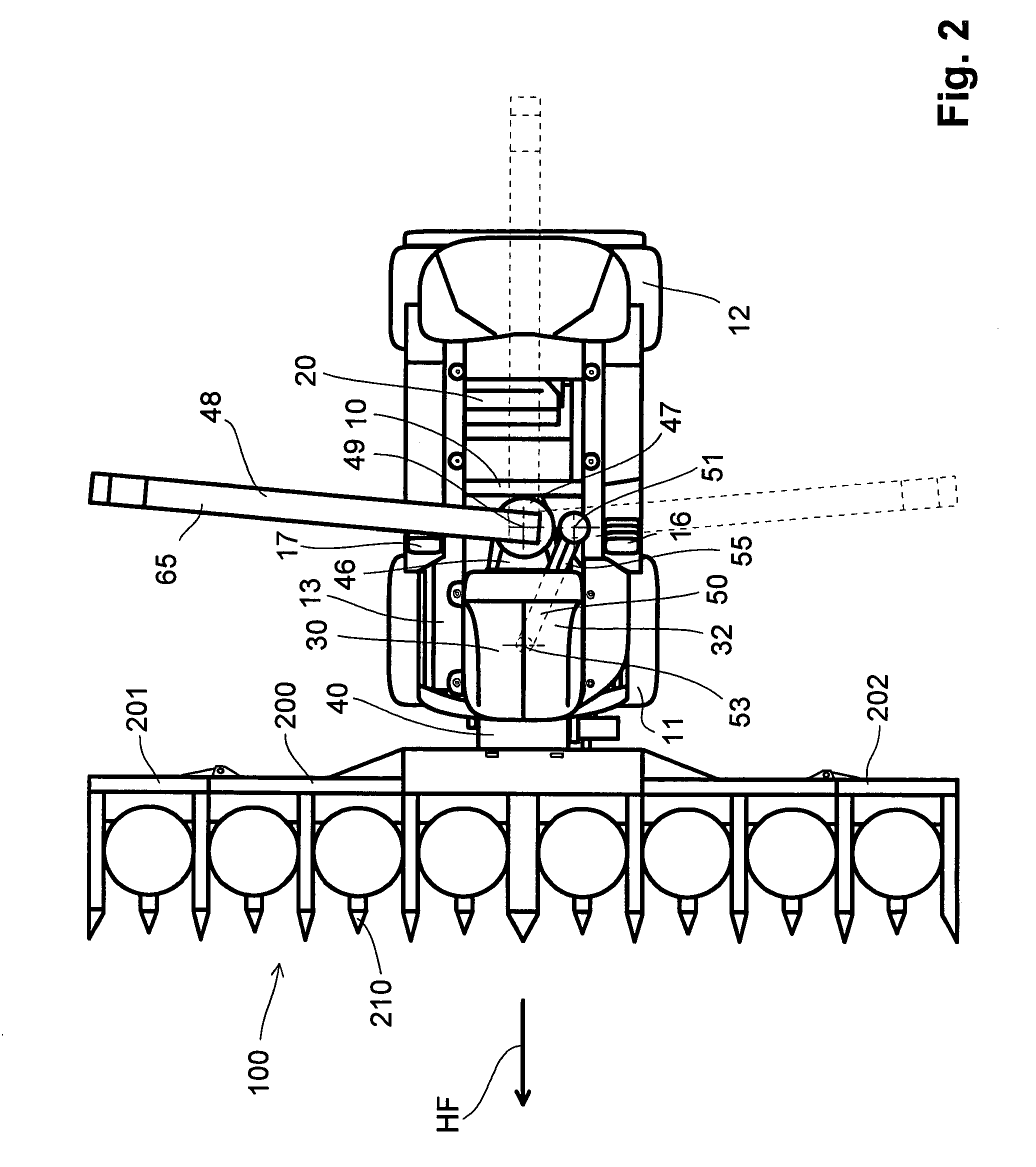
[0033]In a street operational position 31 the operator's cabin 30 is located between substantially a first axle unit 12 and the lower discharge chute 46, and the view of the operator for controlling is oriented in direction of the first axle 12. The operator's cabin 30 is placed on a turning device 50 which is turnable horizontally about a vertical pivot axis of rotation 51. The turning device 50 is formed as a longitudinally-displaceable straight turning arm 55 with an outer end, on which the operator's cabin 30 is supported turnably around the vertical turning axis of rotation 53. The axis of rotation 51 and the turning ...
PUM
 Abstract
Description
Claims
Application Information