Projectile flight altering apparatus

a technology of flight altering and projectiles, applied in the direction of aerial display rockets, weapons, fireworks, etc., can solve the problems of reducing the aerodynamic load, unable to apply braking action without deploying a second independent mechanism, and the pivoting means are subject to breakage, etc., to achieve the effect of reducing and dispersing aerodynamic load

Inactive Publication Date: 2006-02-28
UNITED STATES OF AMERICA THE AS REPRESENTED BY THE SEC OF THE ARMY
View PDF2 Cites 27 Cited by
  • Summary
  • Abstract
  • Description
  • Claims
  • Application Information

AI Technical Summary

Benefits of technology

[0005]A flight altering apparatus for attachment to a projectile, in accordance with the present invention, includes a frame member and a plurality of fins each connected to the frame member by a pivot and surrounding the projectile. A caging arrangement is provided to maintain the fins in ...

Problems solved by technology

The pivoting means are subject to breakage when deployed into the airstream and in order to prevent such breakage the fins and pivots must be rel...

Method used


Image

  • Projectile flight altering apparatus
  • Projectile flight altering apparatus
  • Projectile flight altering apparatus

Examples


Embodiment Construction

[0026]In the drawings, which are not necessarily to scale, like or corresponding parts are denoted by like or corresponding reference numerals.

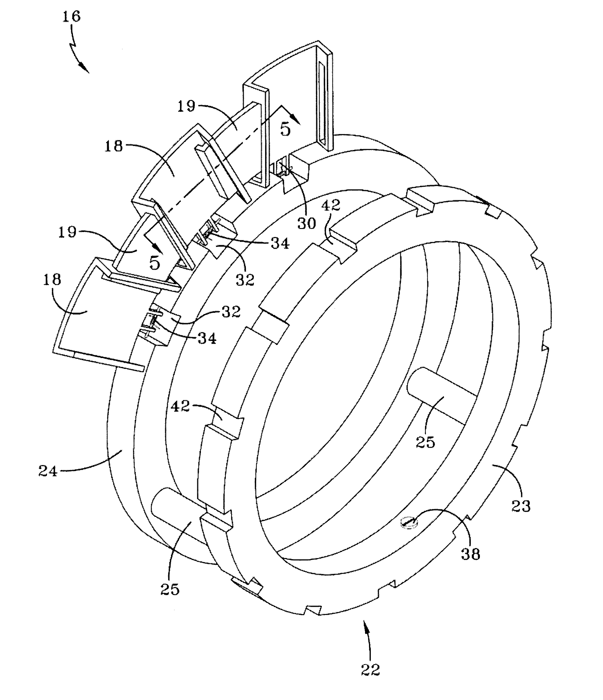
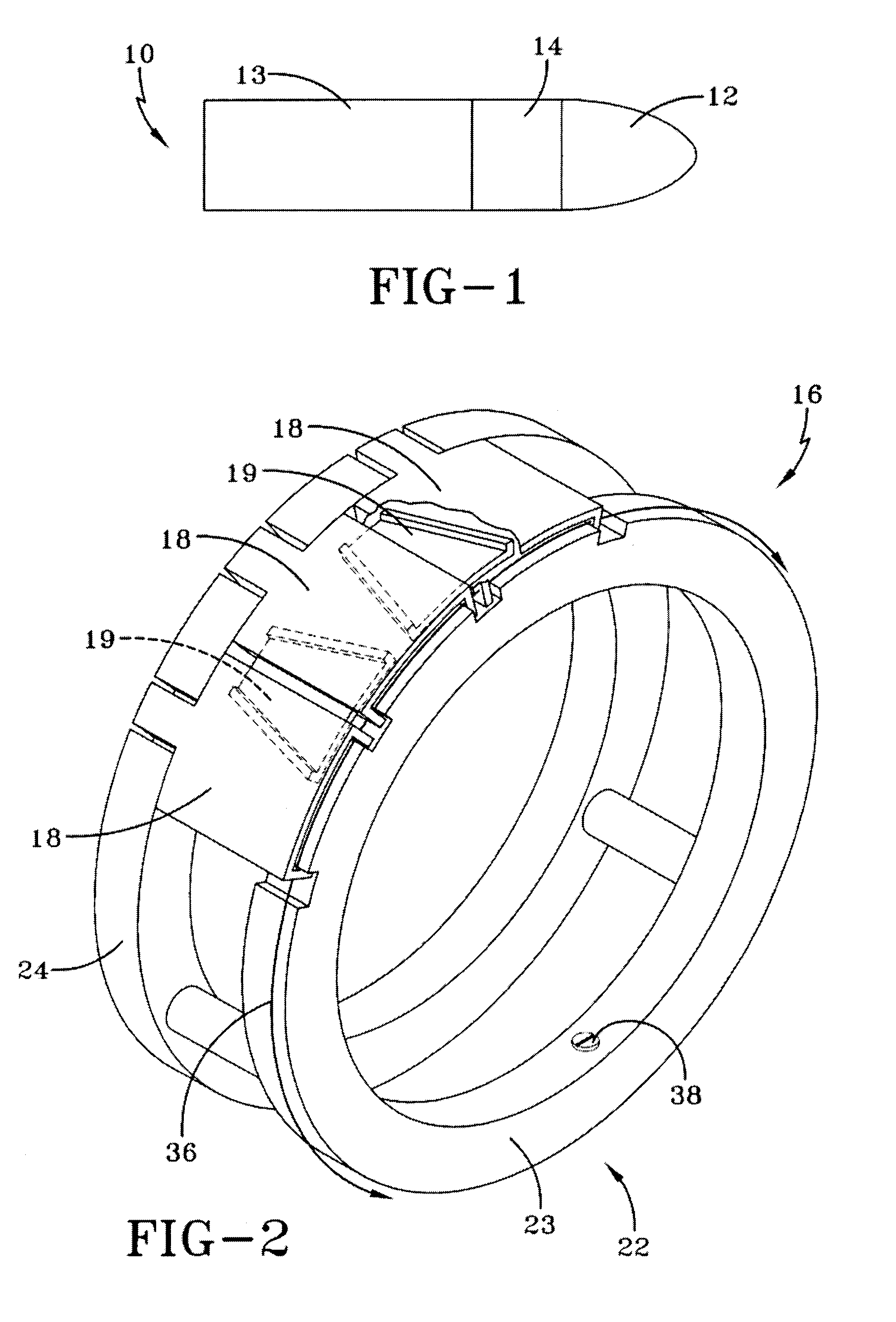
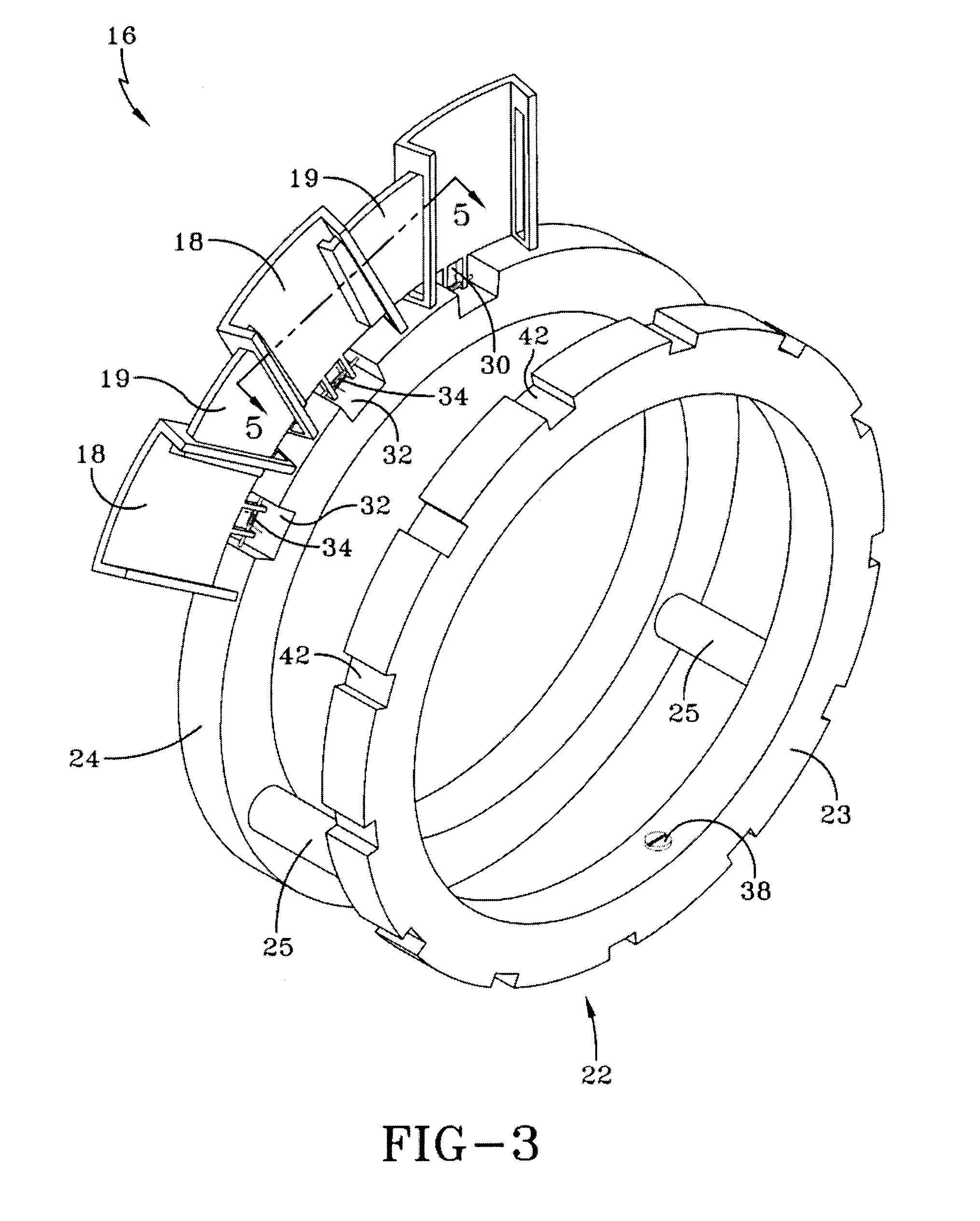
[0027]FIG. 1 illustrates a projectile 10 having a forward removable portion 12 containing a fuze and an electronics section, and an aft portion 13 containing the cargo. The projectile 10 incorporates the present invention depicted as section 14. After the projectile 10 is fired it may be subject to deviation from its planned trajectory by such factors as wind, temperature variations, precipitation, aiming error and the like. In order to modify the trajectory, the fin deployable flight altering apparatus 14 is brought into play.

[0028]If the projectile 10 is being tracked by a remote tracking system, the electronics section of the forward portion 12 may receive commands from the tracking system to cause deployment of the fins. If the electronics section is self-contained with inertial guidance or GPS circuits, as well as a computer, then the el...


PUM


Abstract

A mechanism to alter the flight path of a projectile after launch. A plurality of fins are disposed around the projectile and are held in place by one or more caging wires, depending on fin design. In one embodiment, auxiliary fins are connected to adjacent main fins which are held in a stowed position. When released, the fins deploy and present a continuous surface to the airstream for maximum braking action. In another embodiment, each fin is divided into fin segments which are individually deployable to alter the spin or course of the projectile by deflection. Additionally, all of the fins may be deployed to provide a braking action. All of the fins are tied together to distribute and reduce encountered loads when deployed.

Description

FEDERAL RESEARCH STATEMENT[0001]The inventions described herein may be made, used, or licensed by or for the U.S. Government for U.S. Government purposes.BACKGROUND OF INVENTION[0002]It is often desired to modify the trajectory of a projectile (including missiles) after it has been fired. Conditions such as wind, temperature variations, precipitation, aiming error etc. can cause the projectile to deviate from its intended course, as determined by remote tracking of the projectile or on-board guidance systems. To modify the trajectory, mechanisms are used which are fit onto the projectile and deploy aerodynamic tabs, or fins, while in flight, to impart a corrective action to the projectile. Such corrective action may consist of braking, spin modulation and deflection of the projectile, each action being achieved by a single independent mechanism.[0003]Such mechanisms utilize fins which pivot or eject from a closed inboard position to an open position whereby they extend radially arou...

Claims


Application Information

Patent Timeline
IPC IPC(8): F42B10/00
CPCF42B10/50F42B10/64F42B10/62F42B10/54
Inventor PACCHIA, JOSEPH
Owner UNITED STATES OF AMERICA THE AS REPRESENTED BY THE SEC OF THE ARMY
Why Eureka
Try Eureka