System for the rapid deployment of a concealed object detection system

a technology for concealed objects and detection systems, applied in the field can solve the problems of high installation costs and time, high installation costs, and high cost, and achieve the effects of rapid deployment, effective increase deployment speed and control of deployment surroundings, and rapid deployment of concealed object detection systems

Inactive Publication Date: 2009-04-23
MICROSEMI
View PDF5 Cites 1 Cited by
  • Summary
  • Abstract
  • Description
  • Claims
  • Application Information

AI Technical Summary

Benefits of technology

[0012]In a particular embodiment, a system for the rapid deployment of a concealed object detection system is disclosed. The disclosed system is an approach for deploying a portable, self-contained, concealable, rapid deployment, concealed object detection system using pre-engineered and pre-manufactured components to effectively increase the deployment speed and control the deployment surroundings providing a known and successful environment in which a concealed object detection system camera can operate.
[0013]One particular advantage provided by embodiments of the system for the rapid deployment of a concealed object detection system is the highly portable, “on demand” design and construction. Deployment time is measured in minutes instead of hours or days. Another particular advantage provided by embodiments of the system is that the need to adapt the system's cameras to an uncontrolled environment is eliminated. In addition, the system for the rapid deployment of a concealed object detection system can operate as either an entry portal for weapons or contraband detection or as an exit portal for theft prevention or both.
[0014]Another particular advantage provided by embodiments of the system for the rapid deployment of a concealed object detection system is the possibility of covert deployment, either by its rapid deployment nature or by concealing the camera by virtue of its minimal footprint and deployment requirements. Accordingly, the deployment of the CODS equipment is completed without tools, simplifying and speeding deployment and re-deployment. Further, the CODS equipment can be powered using an independent on-board battery supply so that deployment of the CODS is possible away from standard utility service (e.g., in a field, forest, desert or hostile environment).
[0015]Another advantage provided by embodiments of the system is that the removable cover can store ancillary equipment like cables, batteries, mast poles, cross members, laptop computer, awning cables, ground stakes and / or fabric material for walls and awning. In addition, the removable cover of the system can be used as a podium or laptop computer stand.

Problems solved by technology

In addition, security systems are used in harsh environments such as border control or field military operations.
The harsh and uncontrolled environments require that the prior art CODS must be adapted for each installation to provide the proper contrast between the environment and a subject so that the camera can detect concealed objects, which is expensive and time consuming.
Another shortcoming is that the prior art CODS are dependent on existing utilities and on-site support, which is not always available for the CODS installation in a harsh environment.
Another need exists in the art for a system for the rapid deployment of a concealed object detection system that provides a stable, standard platform for deployments across extremely variable environments, resulting in lower installation costs and time, and simpler construction and support due to the standardized methodology.

Method used


Image

  • System for the rapid deployment of a concealed object detection system
  • System for the rapid deployment of a concealed object detection system
  • System for the rapid deployment of a concealed object detection system

Examples


Embodiment Construction

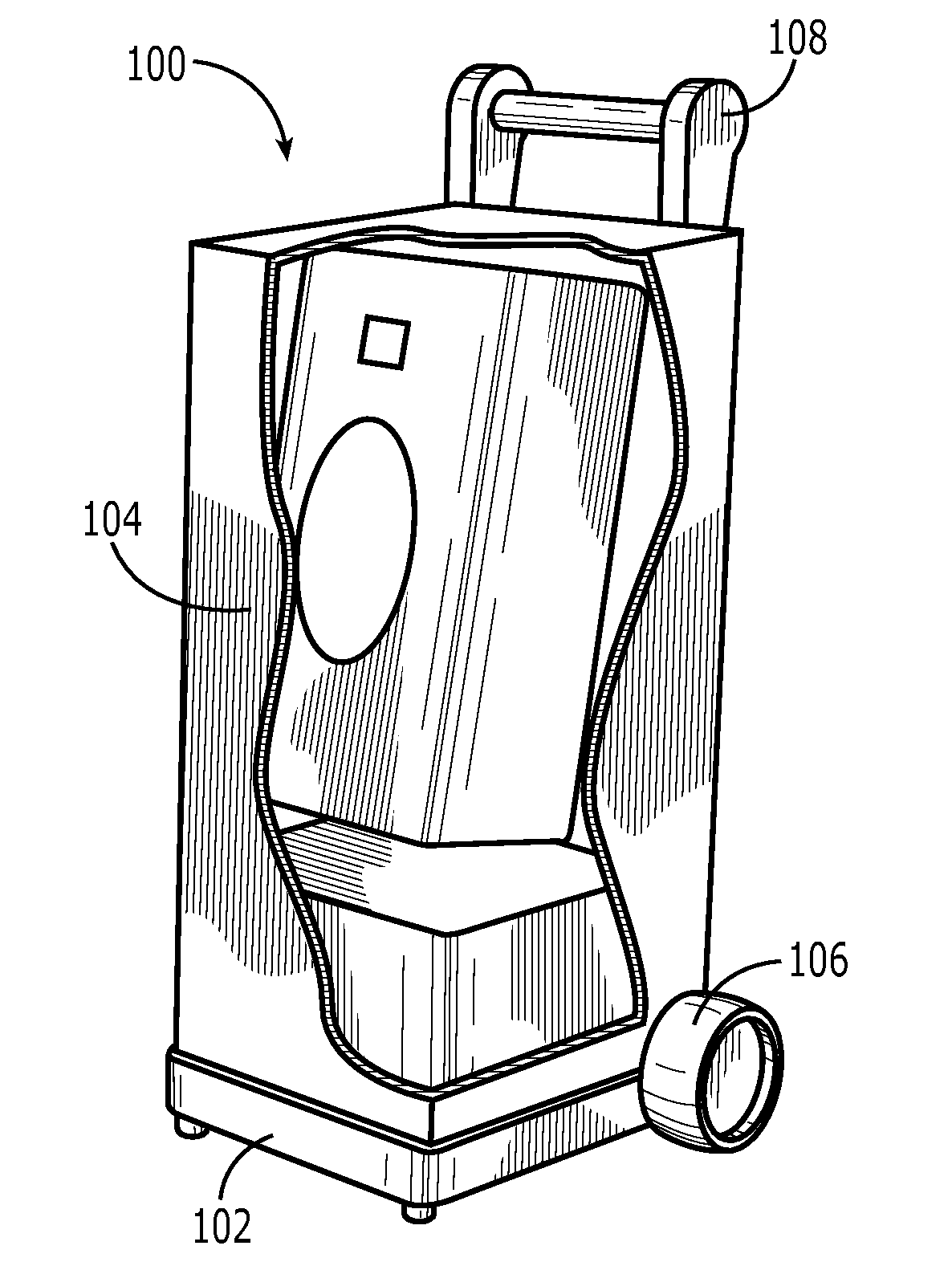
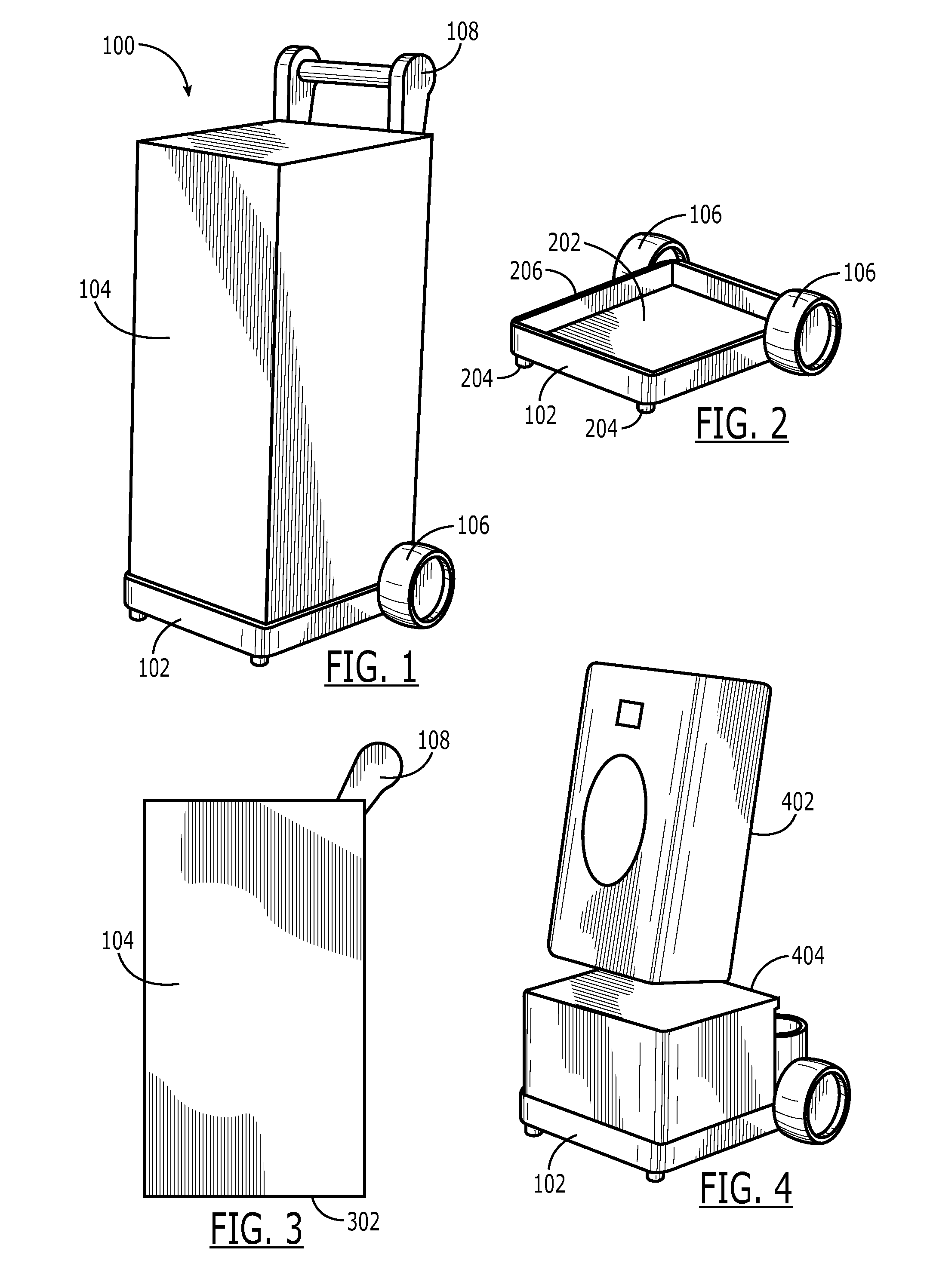
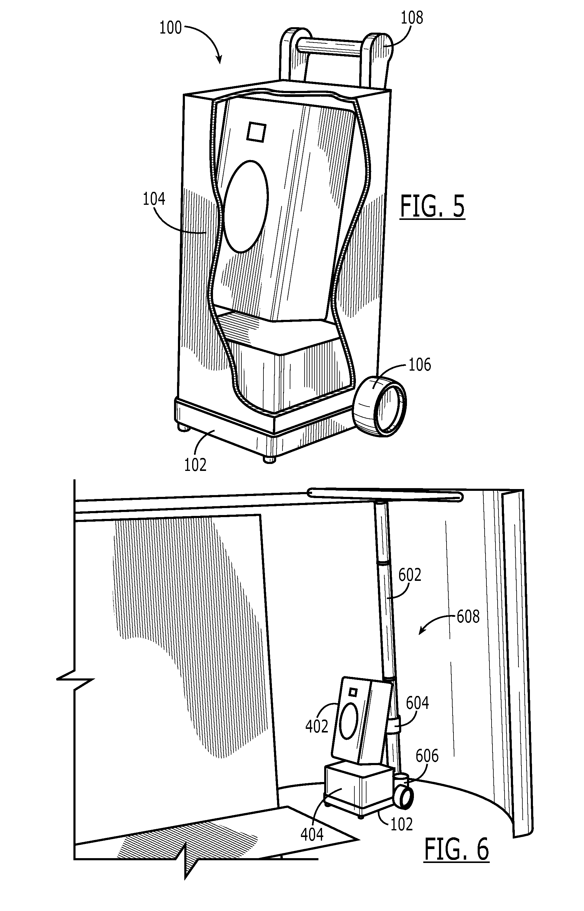
[0023]A system for the rapid deployment of a concealed object detection system is disclosed. The system provides effective control of deployment surroundings and provides a known and successful environment in which the CODS equipment (e.g., millimeter wave camera) can operate. Several components, techniques, technologies and methodologies including external millimeter wave energy mitigation, peripheral motion or clutter mitigation, test subject isolation, motion and flow control, threat containment, weather protection, decorative presentation, blast mitigation, and others may each be used separately, or in combination, with the system.

[0024]In a particular embodiment, the system includes a concealed object detection system that is adapatable for use with transportable screens or walls to mitigate ambient millimeter wave energy and simultaneously control the traffic flow and imaging field of view of the subjects passing in front of the camera(s). The system includes as least one CODS...


PUM


Abstract

A system for the rapid deployment of a concealed object detection system (CODS) is disclosed. In a particular embodiment, a base having side walls about its periphery extending upwards are adapted to secure CODS camera and equipment within the base. The base includes a rolling means disposed along a rear edge so that the CODS equipment is easily transported to the desired location. A removable cover is adapted to slide over the CODS camera and equipment and abut the periphery of the base. Flexible planar material having blast mitigation properties is stored with the removable cover and is deployed to form an inspection area for the CODS camera. The system provides a standard platform for deployments of concealed object detection systems across extremely variable environments.

Description

I. CROSS REFERENCE TO RELATED APPLICATIONS[0001]This application claims the benefit of U.S. Provisional Application No. 60 / 917,436 filed May 11, 2007. The disclosure of the provisional application is incorporated herein by reference.II. FIELD[0002]The present invention relates in general to the field of concealed object detection, and in particular to a system for the rapid deployment of cameras such as millimeter wave cameras that are utilized in concealed object detection systems (CODS).III. DESCRIPTION OF RELATED ART[0003]Security systems can be found at airports, train stations, arenas, construction sites, and other public, private, commercial and industrial facilities. In addition, security systems are used in harsh environments such as border control or field military operations. A passive millimeter wave camera is one type of CODS. The passive millimeter wave camera detects radiation that is given off by all objects. The technology works by contrasting the millimeter wave sig...

Claims


Application Information

Patent Timeline
Patent Type & Authority Applications(United States)
IPC IPC(8): G05B19/00
CPCG01V9/00
Inventor DALY, ROBERT PATRICKREINPOLDT, III, WILLEM H.
Owner MICROSEMI
Why Eureka
Try Eureka