Stent

a technology for prostheses and stents, applied in the field of stents, can solve the problems of general undesirable fishscaling, the attachment of bars of the carrier structure, etc., and achieve the effect of facilitating surface coverag

Active Publication Date: 2006-02-28
BIOTRONIK MESS UND THERAPIEGERAETE GMBH & CO
View PDF20 Cites 109 Cited by
  • Summary
  • Abstract
  • Description
  • Claims
  • Application Information

AI Technical Summary

Benefits of technology

The new type of stent described in this patent has unique characteristics compared to existing stents on the market. It expands differently when used, which makes it more effective at treating certain medical conditions. Additionally, the stent provides better protection against complications like blood clots, without sacrificing effectiveness or causing damage to surrounding tissues.

Problems solved by technology

The technical problem addressed in this patent is the development of a new stent design that meets various requirements including easy placement, high flexibility, minimal recoil, effective carrier force, optimal surface covering, and favorable bar attachment. Existing stent designs have limitations in meeting all these requirements simultaneously, leading to the need for improved options.

Method used


Image

  • Stent
  • Stent
  • Stent

Examples


Embodiment Construction

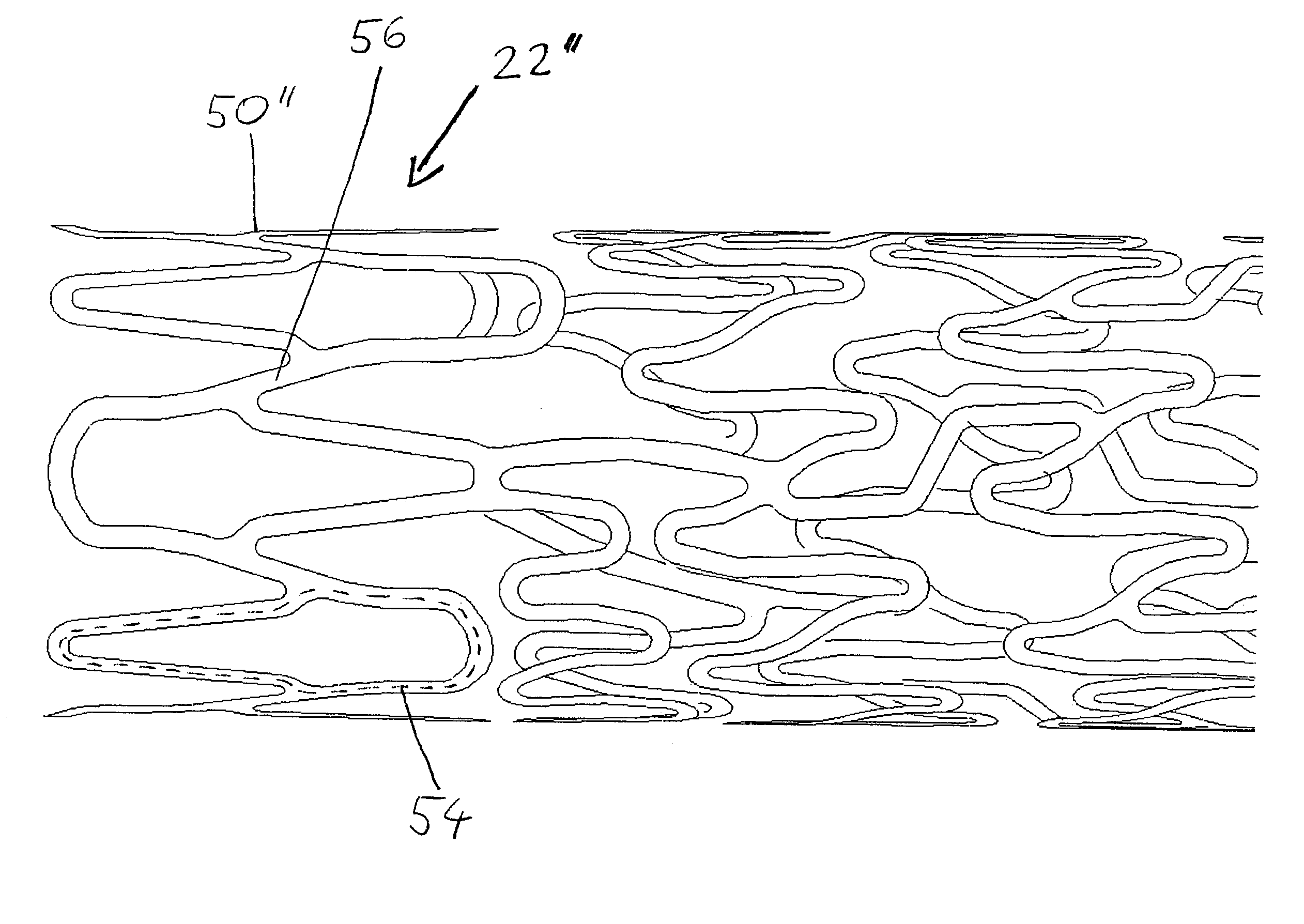
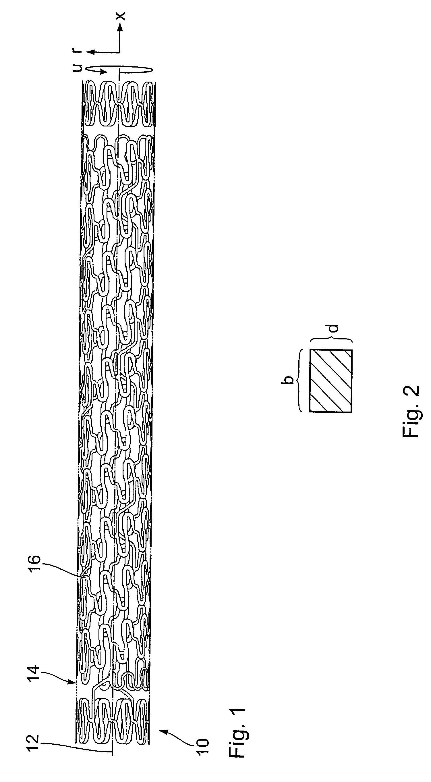
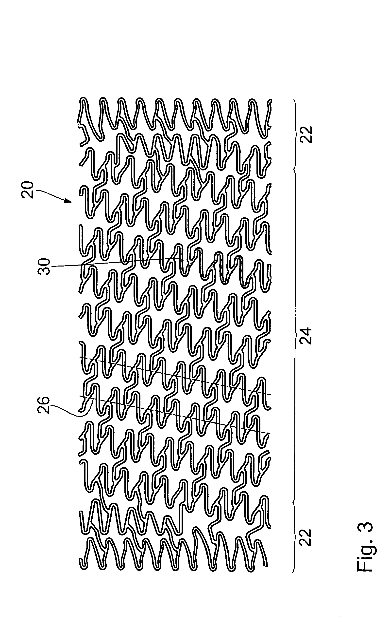
[0033]FIG. 1 shows a stent 10 having a longitudinal axis 12 and a peripheral wall 14 which extends around the longitudinal axis 12 and which forms a carrier structure for the stent 10. The peripheral wall 14 and the carrier structure formed thereby are formed by bars 16.

[0034]The geometry of the peripheral wall 14 will be described by using the co-ordinates shown in FIG. 1, more specifically x as the longitudinal direction of the stent, r as co-ordinates extending radially with respect to the longitudinal direction x and u as co-ordinates extending in the peripheral direction of the stent 10.

[0035]It can be seen from the view in cross-section through a bar 16 as illustrated in FIG. 2 that the bar geometry can be described by a bar thickness d and a bar width b. In this case, the bar thickness d is the dimension of a bar in the radial direction r with respect to the stent while the bar width b represents the dimension of a bar in the direction of a peripheral surface formed by the pe...


PUM


Abstract

The invention concerns a stent comprising a longitudinal axis (12) and a peripheral wall (14) which is formed at least over a part of the length of the stent (10) by a lattice-like carrier structure (24) which is open at two ends. The carrier structure includes at least one bar (16) extending helically around the longitudinal axis in such a way as to provide a helical primary shape (26) for the peripherally extending bar with more than one helical turn. Besides the helical primary shape (26) the bar has a zigzag-like or meander-shaped secondary shape (30) with reversal points and associated reversal portions (32), between which extend bar portions (34) of the peripherally extending bar with an extension component in the longitudinal direction of the stent. The carrier structure further includes connecting bars (40) which respectively bridge over a helical turn of the helical primary structure and which at their two longitudinal ends attach to the bar portions (34) of the helical primary shape between two respective adjacent reversal points.

Description


Claims


Application Information

Patent Timeline
Owner BIOTRONIK MESS UND THERAPIEGERAETE GMBH & CO
Why Eureka
Try Eureka