
Nanoparticle coated electrode and method of manufacture

a technology of nanoparticles and electrodes, applied in the direction of electrochemical coatings, cell components, manufacturing tools, etc., can solve the problems of high cost of particle filter replacement, large expenditure of fleet owners for replacement of older diesel engines with new engines, and low pollution of such fuel cells, etc., to achieve good connection, increase the rate of electrochemical reaction, and enhance the surface area

Inactive Publication Date: 2011-12-08
QUANTUMSPHERE
View PDF3 Cites 0 Cited by
  • Summary
  • Abstract
  • Description
  • Claims
  • Application Information

AI Technical Summary

Benefits of technology

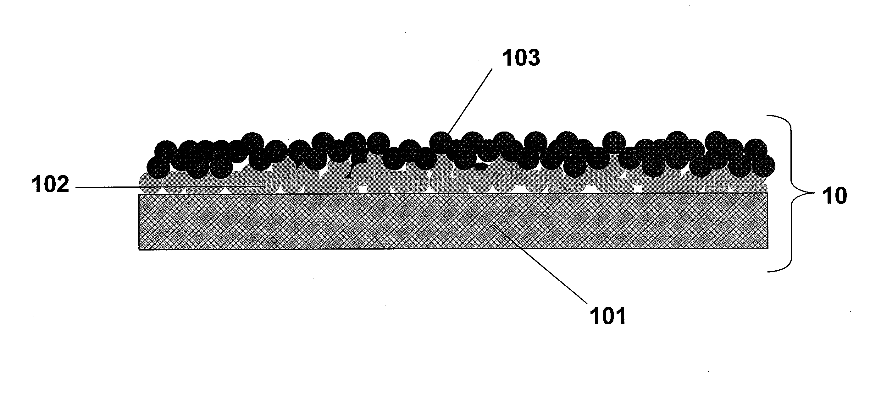
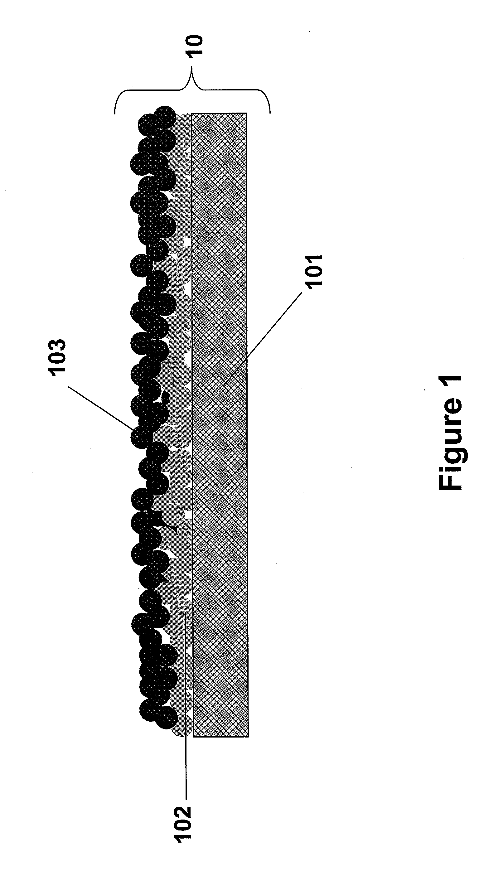
[0012]The primary layer may comprise nanoparticles of copper, silver, or gold. It is desirable that the primary metal nanoparticle coating be evenly distributed on the metallic substrate and have good surface coverage. This may be accomplished by way of an inventive method for applying nanoparticle coatings to the electrode substrate. In one application, the inventive method comprises preparing a dispersion of nanoparticles in a solvent. Desirably, but not necessarily, the solvent is volatile, and is easily evaporated at temperatures below 300° C. The dispersion of the primary metal nanoparticle coating may be accomplished by a variety of methods, including but not limited to painting, spraying, or screen printing. Following application, the primary coating can be followed by heat treatment between 500-1000° C. to sinter metal nanoparticles together to provide structural integrity.
[0014]When metal nanoparticles are layered onto an electrically conductive substrate surface, the surface area of that electrode is increased significantly relative to that of the substrate alone. The primary nanoparticle layer provides enhanced surface area to the substrate and allows good connection between the substrate and secondary layer of nanoparticles. This secondary layer may be the most active layer of the electrode, and can provide for an increase in the rate of electrochemical reactions, thus, improving efficiency. These electrodes may provide both a cost and performance improvement compared to traditional electrodes in electrochemical systems, such as an electrolyzer or fuel cell.

Problems solved by technology

Unfortunately, particulate matter filters are costly and require intermittent cleaning, which dumps the PMs into landfills instead of the air.
Replacement of older diesel engines with new engines would require a massive expenditure for fleet owners.
Because these fuels are not burned, pollution from such fuel cells is quite low or non-existent.
In many conventional devices, significant efficiency loss stems from low catalyst utilization in the electrodes, cell resistance, inefficient movement of electrolyte, and inefficient collection of reaction products from the electrolyte.
While this strategy increases efficiency, it also lowers the amount of products that can be produced at a given time.
While this process is relatively low cost, it is not environmentally friendly.
Without further purification to remove polluting CO and CO2, hydrogen remains an unacceptable fuel alternative when generated by steam reformation, as is a poison for many fuel cell catalysts.
The process of effective purification necessary to make it more ecologically acceptable, however, makes it cost prohibitive.
Currently, electrolysis is too expensive to compete with steam reformation due to low efficiency and expensive catalyst electrodes.

Method used


Image

  • Nanoparticle coated electrode and method of manufacture
  • Nanoparticle coated electrode and method of manufacture
  • Nanoparticle coated electrode and method of manufacture

Examples


example 1

Preparation of a Nanoparticle Electrode

[0030]About 2 grams of nano-silver powder was blended into 5 grams of ethylene glycol. The resulting primary nanoparticle dispersion was stirred for five minutes. Nickel was cut to the desired electrode shape and coated with the dispersion. The nickel with silver layer was heated to evaporate off the solvent and allowed to cool. The process was repeated an additional 3-4 times. After the final primary layer was applied, the coated nickel plate was placed in a furnace at 900° C. for one hour and then allowed to cool. A second metal nanoparticle dispersion was prepared by combining 0.5 grams of nano nickel particles with 0.5 grams of nano iron particles into 3 grams of ethylene glycol. The resulting dispersion was stirred for five minutes. The metallic plate coated with the primary nanoparticle coating was layered with this dispersion. The secondary nanoparticle layer was heated to evaporate off the solvent and allowed to cool. The process was re...

example 2

Electrode Performance

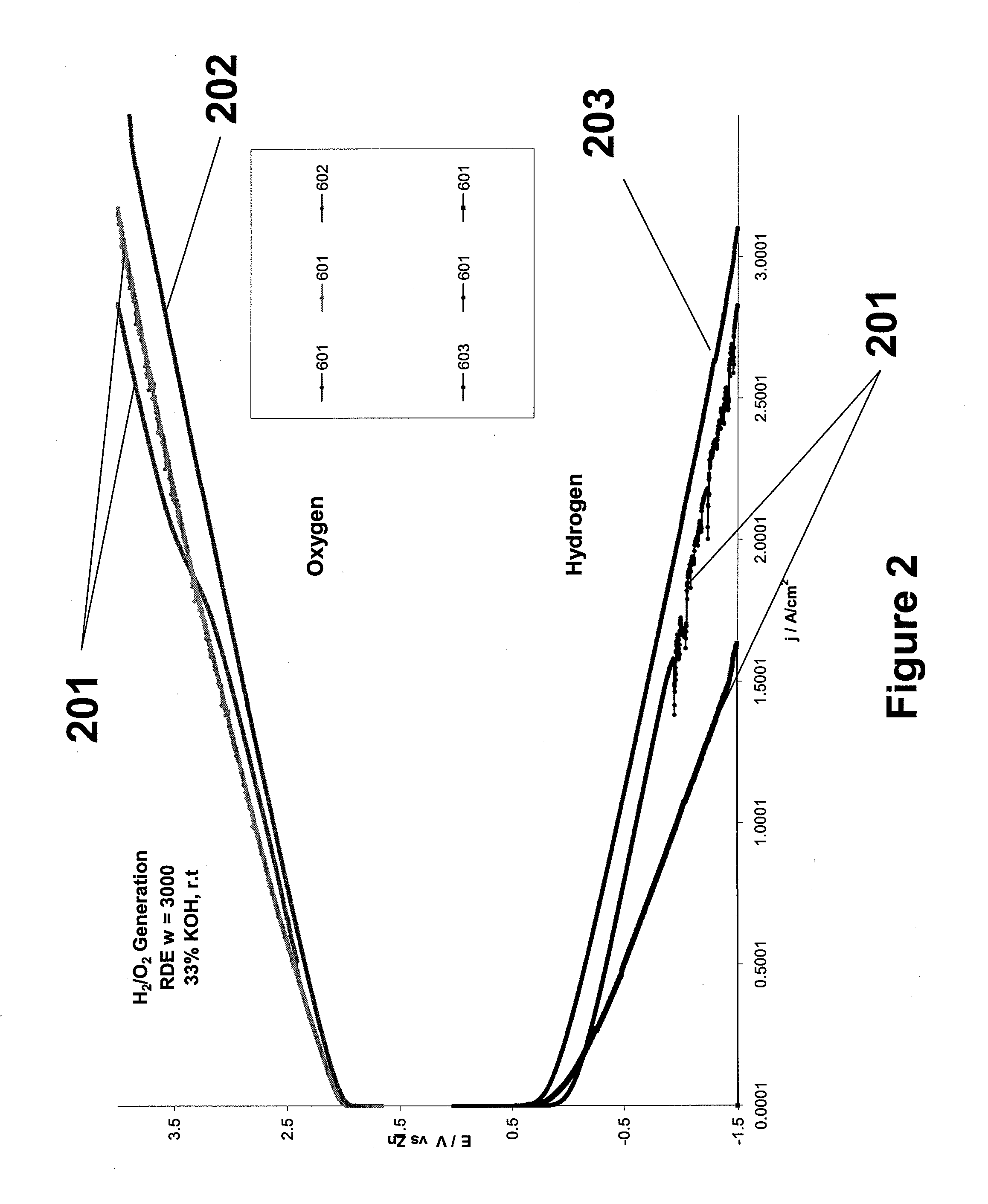
[0031]Cathodes were tested using a half-cell apparatus to independently test the electrode activity for hydrogen and oxygen generation. Electrolyte was a 33% KOH solution against a zinc-wire reference electrode. FIG. 2 shows a set of galvanostatic tests at 1 A / cm2 for oxygen generation and a set for hydrogen generation. The most inefficient electrodes, shown as lines 201 are the lowest and highest lines on the hydrogen and oxygen curves, respectively. The most efficient electrodes were the nanoparticle coated electrodes. Lines 202 and 203 illustrate this enhanced performance.


PUM

PropertyMeasurementUnit
diameteraaaaaaaaaa
temperatureaaaaaaaaaa

Abstract

An electrode comprising a primary and secondary metal nanoparticle coating on a metallic substrate is prepared by dispersing nanoparticles in a solvent and layering them onto the substrate, followed by heating. The enhanced surface area of the electrode due to the catalytic nanoparticles is dramatically enhanced, allowing for increased reaction efficiency. The electrode can be used in one of many different applications; for example, as an electrode in an electrolysis device to generate hydrogen and oxygen, or a fuel cell.

Description

CROSS-REFERENCE TO RELATED APPLICATION[0001]This application is a continuation of U.S. patent application Ser. No. 11 / 868,152, filed Oct. 5, 2007, the entire contents of which are incorporated herein by reference.BACKGROUND OF THE INVENTION[0002]1. Technical Field[0003]The inventions disclosed herein relate generally to catalysts for electrochemical reactions, and specifically to, for example, electrodes for use in electrolysis and fuel cell devices.[0004]2. Related Art[0005]Hydrogen is a renewable fuel that produces zero emissions when used in a fuel cell, and significantly reduces emissions (while improving fuel economy) when injected into the fuel stream of an internal combustion engine such as a diesel engine. It is well known that the combustion of hydrogen and oxygen gas in a diesel or gasoline fuel stream improves fuel efficiency and horsepower because hydrogen and oxygen burn faster and hotter than diesel or fossil fuels, dramatically boosting combustion efficiency and more ...

Claims


Application Information

Patent Timeline
Patent Type & Authority Applications(United States)
IPC IPC(8): C25B11/06C25B11/08B05D5/12H01M4/90H01M4/88C25B11/04H01M4/86
CPCC25B11/00C25B11/0478H01M4/8657Y02E60/50H01M4/8882H01M4/90H01M4/8828C25B11/091
Inventor MCGRATH, KIMBERLYDOPP, ROBERTCARPENTER, R. DOUGLAS
Owner QUANTUMSPHERE
Learn More