Method for manufacturing a potted bundle of hollow fibers

a manufacturing method and technology of hollow fibers, applied in the field of manufacturing a potted bundle of hollow fibers, can solve the problems of mandrel interference with potting, inadequate coiled hollow fiber devices, and only recently disclosed coiled hollow fiber modules

Inactive Publication Date: 2006-02-28
MILLIPORE CORP
View PDF6 Cites 84 Cited by
  • Summary
  • Abstract
  • Description
  • Claims
  • Application Information

AI Technical Summary

Benefits of technology

[0009]It is an object of the present invention to provide better distribution of the potting compound, especially to the inner layers of fibers in a hollow fiber bundle.
[0011]It is an object of the present invention to prevent the potting compound from wicking up into the fibers or up the side of the mandrel.

Problems solved by technology

However, coiled hollow fiber modules were only recently disclosed.
While this method is appropriate for straight hollow fibers, it has proven inadequate for the coiled hollow fiber devices, especially the multilayered coiled hollow fiber devices produced by the inventor's colleagues.
As a mandrel is preferably-used to produce these the multi-layered coiled hollow fiber devices, the mandrel interfered with the potting.
Since the fibers did not pot properly, the performance of the module does not match the performance outputs predicted by the algorithms.

Method used


Image

  • Method for manufacturing a potted bundle of hollow fibers
  • Method for manufacturing a potted bundle of hollow fibers
  • Method for manufacturing a potted bundle of hollow fibers

Examples


first embodiment

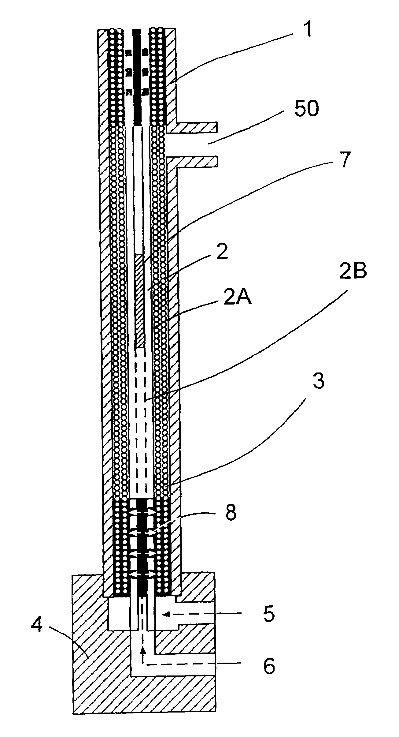
[0020]FIG. 1 illustrates the present invention. The shell or housing 1 contains a mandrel 2 having one or more layers of hollow fibers 3 wrapped around its outer surface 2A. This device is placed on a preformed block 4 that has an outer layer potting fill hole 5 and a center rod potting fill hole 6. The mandrel 2 as shown has a hollow center 2B and includes a plastic inset or plug 7 and through holes 8 in fluid communication with the inner layers of hollow fibers 3.

[0021]The structure is then inserted into the preformed block 4 and the inner layer fill hole 6 is then filled with enough potting compound such as epoxy to force the compound through the through holes 8 and into the fiber bundle to form a pot of predetermined height. The outer layer fill hole 5 is also filled with potting compound preferably to that same height. Preferably, the inner hole 6 is filled first followed by the outer hole 5 to ensure that adequate flow around all fibers is achieved. Alternatively, both may be ...

second embodiment

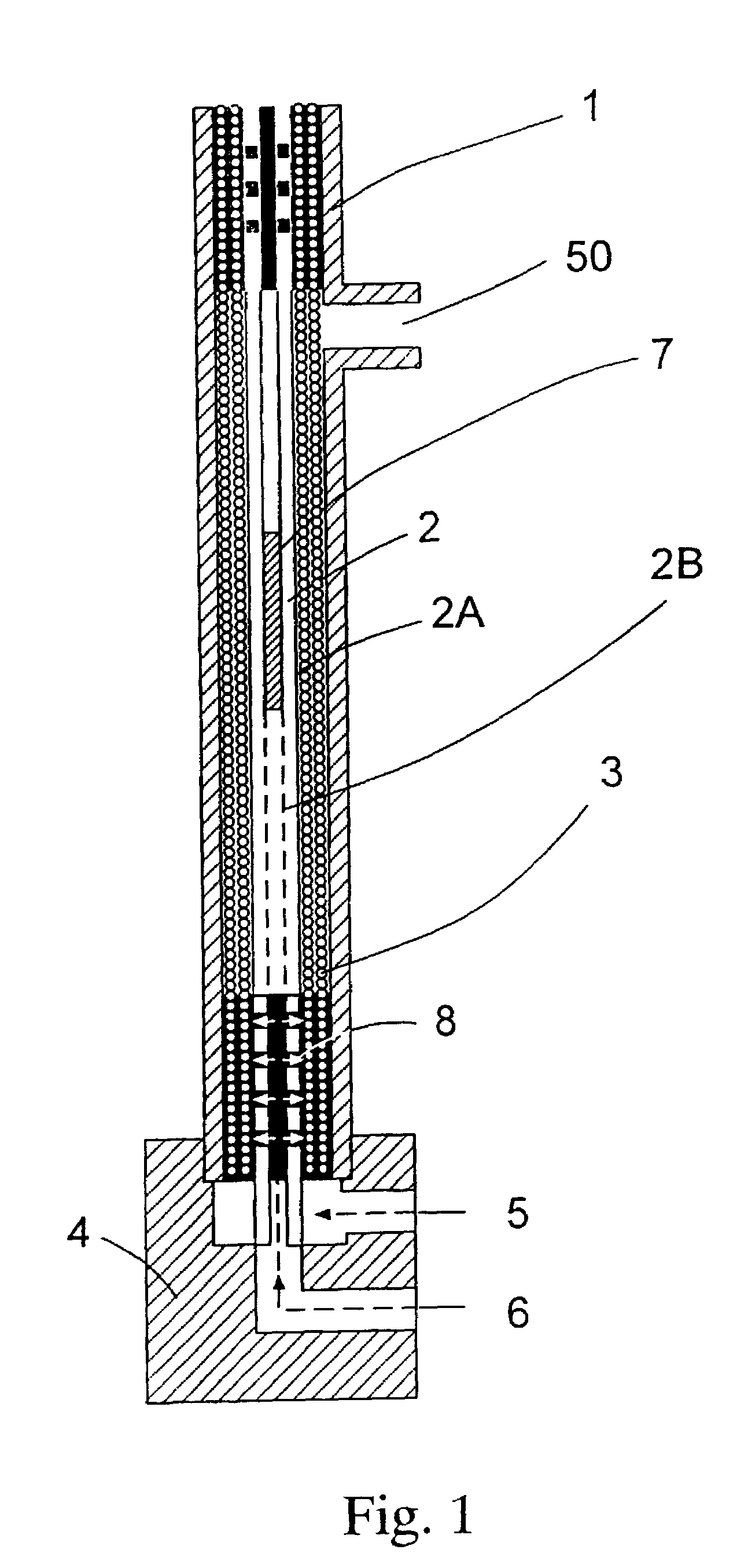
[0023]FIG. 2 shows the present invention. In this embodiment it is applied to straight hollow fibers. The shell or housing 10 contains a mandrel 11 having one or more layers of straight hollow fibers 12 surrounding the outer surface 13 of the mandrel 11. This device is placed on a preformed block 14 that has an outer layer potting fill hole 15 and a center rod potting fill hole 16. The mandrel 11 as shown has a hollow center 17 and includes a plastic inset or plug 18 and through holes 19 in fluid communication with the inner layers of hollow fibers 12.

[0024]Potting compound such as epoxy or urethane resin is then flowed into the inner layer fill hole 16 with enough potting compound to force the compound through the through holes 19 and into the fiber bundle to form a pot of predetermined height. The outer layer fill hole 15 is also filled with potting compound preferably to that same height. Preferably, the inner hole 16 is filled first followed by the outer hole 15 to ensure that a...

third embodiment

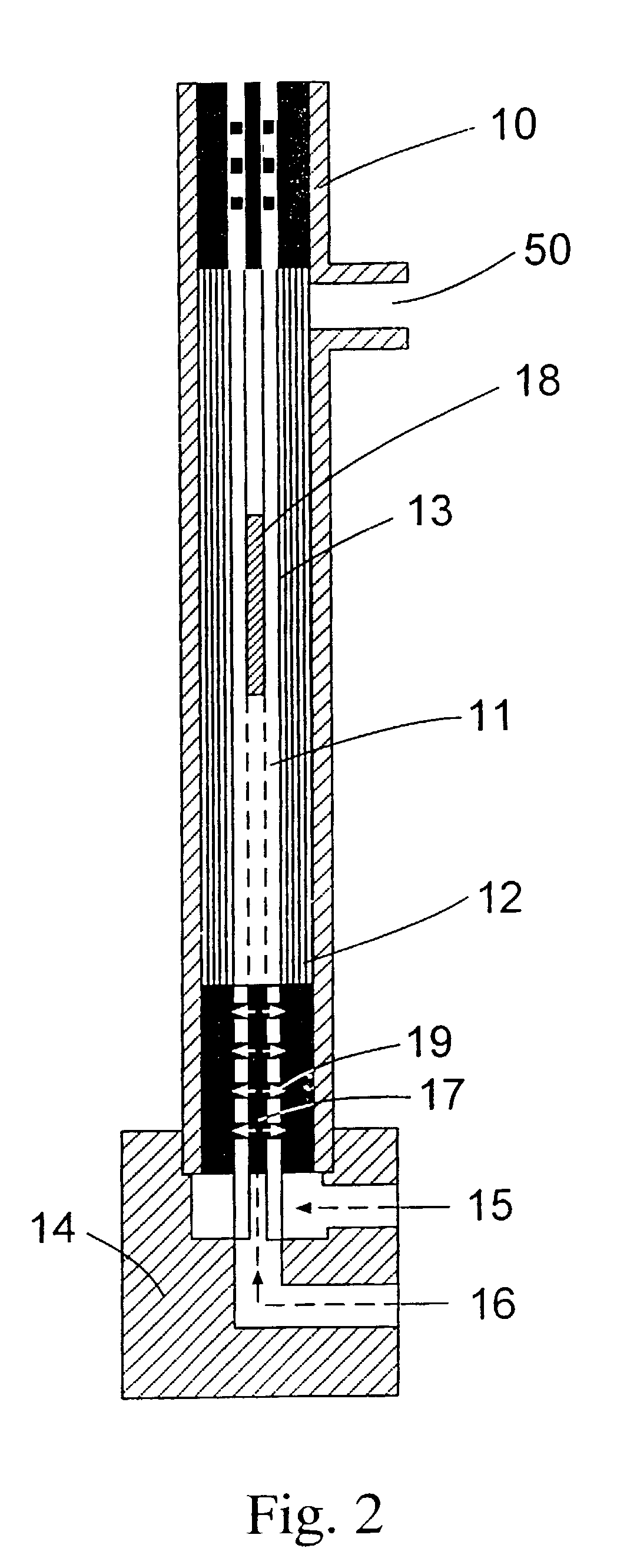
[0025]FIG. 3 shows the present invention. In this embodiment it is applied to straight hollow fibers. The shell or housing 20 contains two short mandrels 21A and B that are equal in length or slightly longer than the area or length of fiber which will be potted. Each mandrel 21A and 21B is located at opposite ends of the shell 20 and have one or more layers of straight hollow fibers 22 surrounding the outer surface 23A and 23B respectively of each mandrel 21A and 21B. This device is placed on a preformed block 24 that has an outer layer potting fill hole 25 and a center rod potting fill hole 26. The mandrels 21A and B as shown each has a hollow center 27 and includes an end cap 28A and 28B and through holes 29A and B in fluid communication with the inner layers of hollow fibers 22.

[0026]Potting compound such as epoxy or urethane resin is then flowed into the inner layer fill hole 26 with enough potting compound to force the compound through the through holes 29A and B and into the f...


PUM

PropertyMeasurementUnit
lengthaaaaaaaaaa
heightaaaaaaaaaa
wettingaaaaaaaaaa

Abstract

The present invention involves a process that includes injecting a potting compound such as an epoxy through a hollow portion (2B) of the central mandrel (2) and onto the inner layer(s) of a multi-layered fiber bundle (3) and through the outside of the bundle and onto the outer layer(s) of the bundle. By potting through the central mandrel (2), the potting compound distributes evenly throughout the inner fibers of the bundle (3). The steps may be sequentially or simultaneously. Preferably it is done as a two-step process, with the first step being to apply the potting compound through the central mandrel (2) and onto the inner fibers first. The second step is to pot around the outer layer of the fiber bundle (3) to finish the process. The resultant product is also disclosed.

Description

[0001]This application claims the benefit of Provisional App. No. 60 / 172,337, filed Dec. 17, 1999.[0002]The present invention relates to a method of potting hollow fibers. More particularly, it relates to a method of potting spiral wound hollow fibers.BACKGROUND OF THE INVENTION[0003]Straight hollow fiber filtration devices are ubiquitous. However, coiled hollow fiber modules were only recently disclosed. See U.S. Pat. No. 5,626,758. Indeed, multi-layered coiled hollow fiber devices were only briefly discussed in U.S. Pat. No. 5,626,758, with no mention of how to assemble or pot the fiber bundles. Devices containing coiled hollow fibers if designed properly are capable of inducing Dean vortices in their inner diameter or lumen. These vortices cause a sweeping of the inner lumen surface disrupting the boundary layer which forms there between the particles or dissolved species which are to be retained inside the fiber and materials and fluids which are to pass through the fibers to th...

Claims


Application Information

Patent Timeline
Patent Type & Authority Patents(United States)
IPC IPC(8): B29C65/70B01D63/00B01D63/02B29C45/14B29C70/72
CPCB01D63/00B01D63/022B29C45/14467B29C45/14786B29C70/72B29C45/14549B29L2031/14
Inventor LOWELL, PAUL
Owner MILLIPORE CORP
Why Eureka
Try Eureka