
Stator winding having two slots per phase per pole

a technology of stator and winding, which is applied in the direction of winding, dynamo-electric components, magnetic circuit shape/form/construction, etc., can solve the problems of increasing the cost of stator, increasing cost and manufacturing complexity,

Active Publication Date: 2006-02-28
BORGWARNER INC
View PDF20 Cites 59 Cited by
  • Summary
  • Abstract
  • Description
  • Claims
  • Application Information

AI Technical Summary

Benefits of technology

[0011]The above, as well as other advantages of the present invention, will become readily apparent to those skilled in the art from the following detailed description of a preferred embodiment when considered in the light of the accompanying drawings in which:

Problems solved by technology

One disadvantage of a six phase high slot fill stator is that it requires six diode pairs (one for each phase).
This increases the cost of the stator due to the high cost of the diode pairs.
This solution have fewer diode pairs, but requires an additional reverse connection between the two conductors, thereby increasing cost as well as manufacturing complexity.
Furthermore, this solution does not address the issue of the standard six pitch winding having high resistance due to the length of the conductor in each six pitch end loop segment.

Method used


Image

  • Stator winding having two slots per phase per pole
  • Stator winding having two slots per phase per pole
  • Stator winding having two slots per phase per pole

Examples


Embodiment Construction

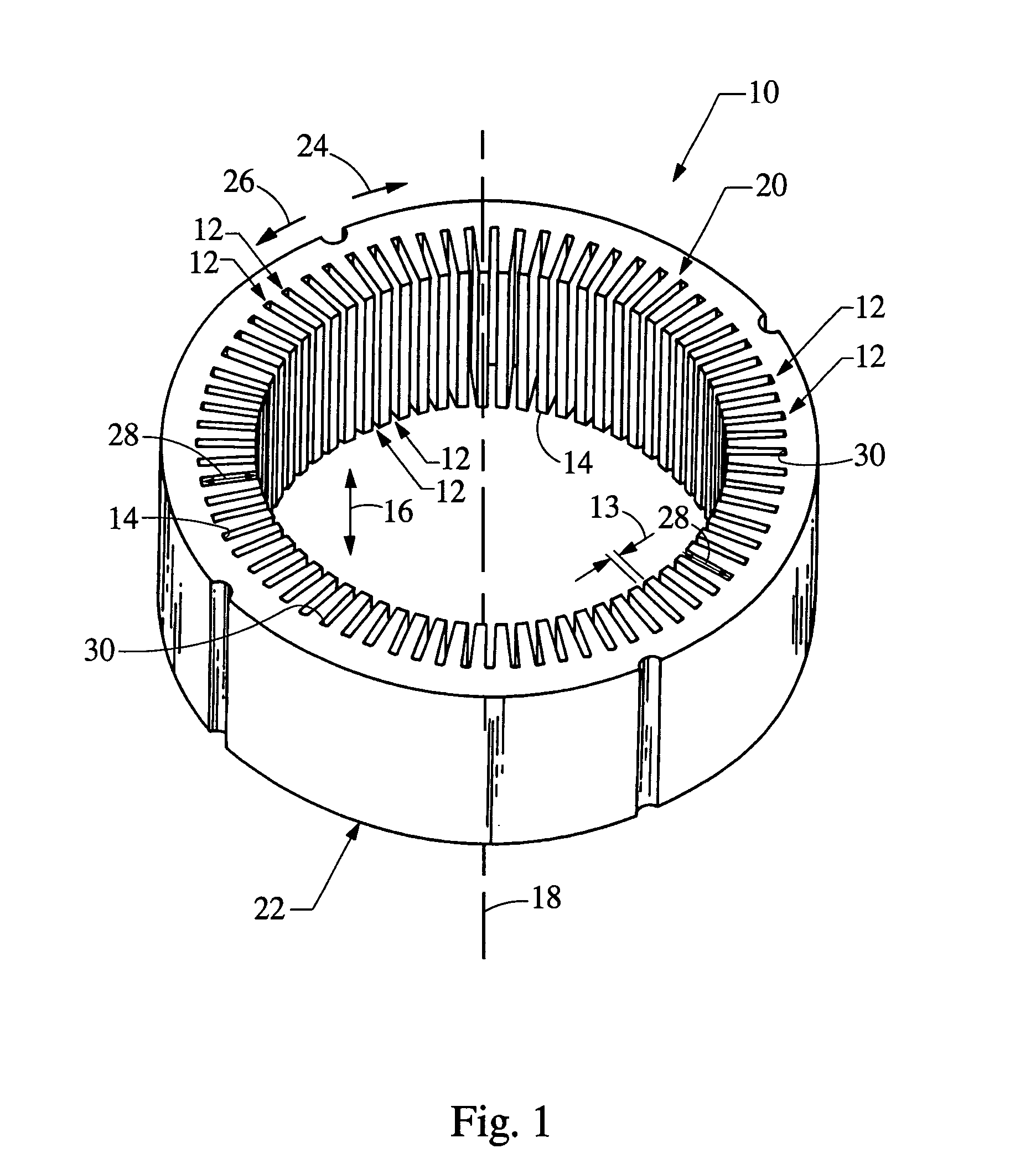
[0024]Referring now to FIG. 1, a generally cylindrically-shaped stator core is indicated generally at 10. The stator core 10 includes a plurality of core slots 12 formed in a circumferential inner diameter 14 thereof. The core slots 12 extend in an axial direction, indicated by an arrow 16, parallel to a central axis 18 of the stator core 10 between a first end 20 and a second end 22 thereof. An axially upward direction is defined as moving toward the first end 20 of the stator core 10 and an axially downward direction is defined as moving toward the second end 22 of the stator core 10.

[0025]Preferably, the core slots 12 are equally spaced around the circumferential inner diameter 14 of the stator core 10. A circumferential clockwise direction is indicated by an arrow 24 and a circumferential counterclockwise direction is indicated by an arrow 26.

[0026]The core slots 12 define a radial depth 28, between ends 30 of the core slots 12 and the inner diameter 14 of the stator core 10. Th...


PUM


Abstract

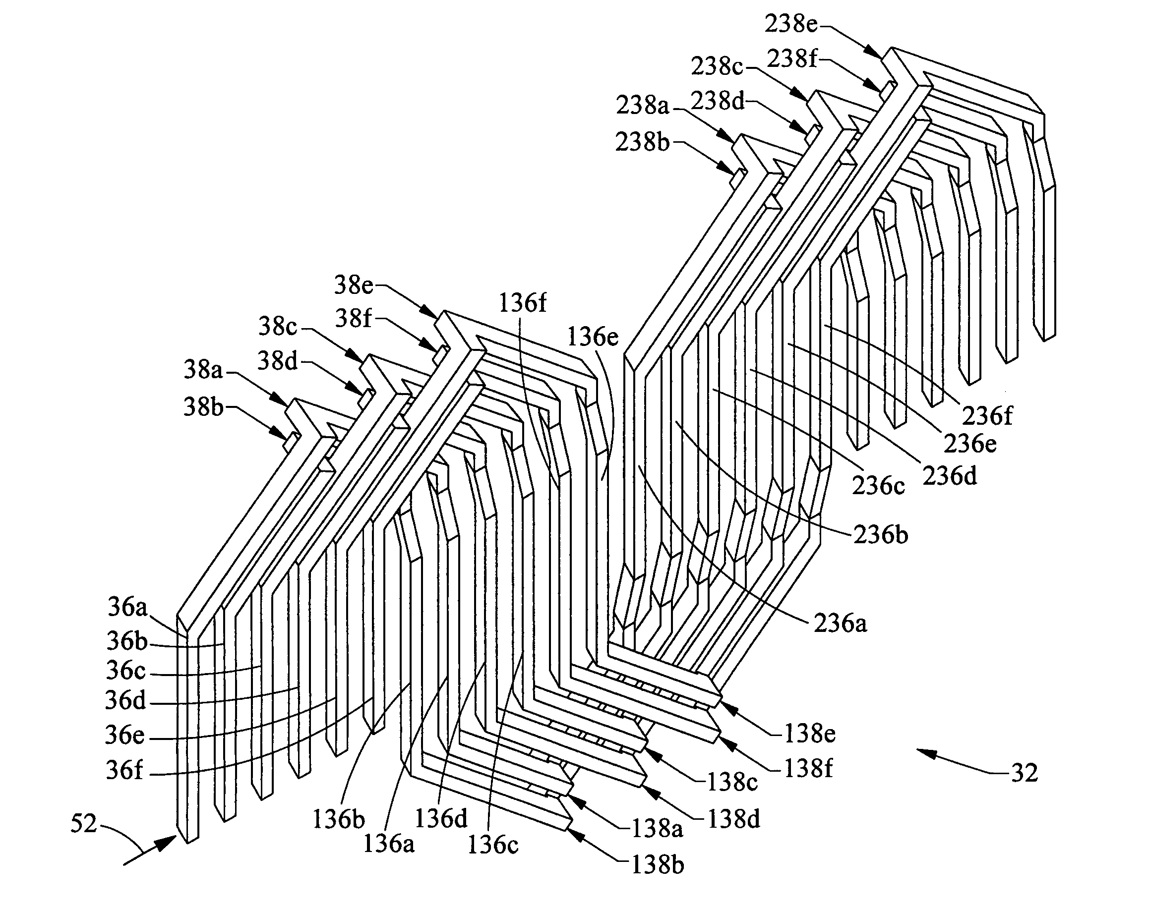
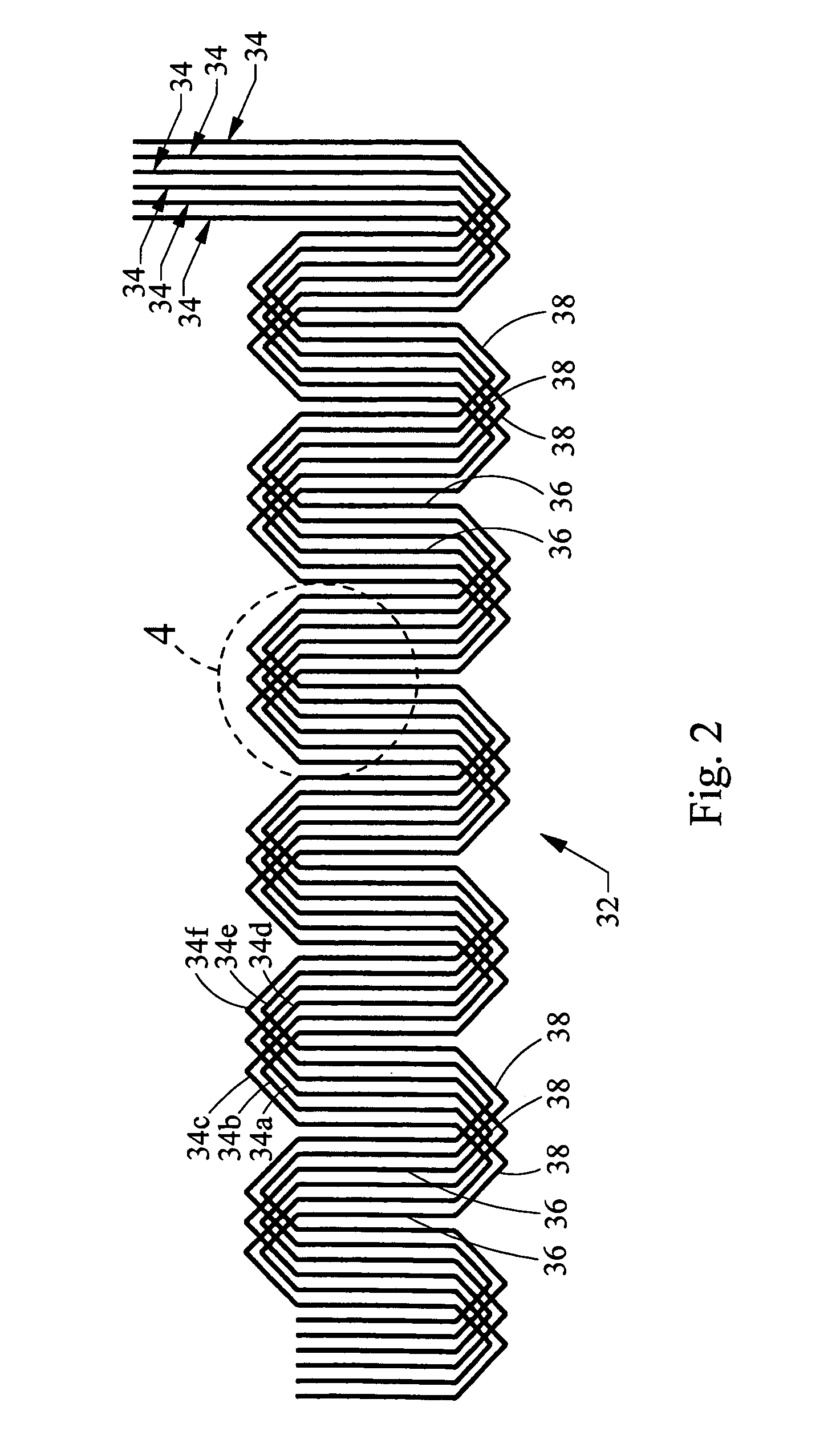
A stator for an electric machine includes a generally cylindrically-shaped stator core having a plurality of circumferentially-spaced and axially-extending core teeth that define a plurality of circumferentially-spaced and axially-extending core slots extending between first and second ends of the stator core. Within the core is a stator winding having a plurality of phases, each of the phases including a pair of conductors connected in parallel and having a plurality of slot segments housed in the core slots. The slot segments are alternately connected at the first and second ends of the stator core by a plurality of end loop segments. The conductors within each pair of each phase are connected in parallel and are in phase with one another such that the stator core has two slots per phase per pole.

Description

FIELD OF THE INVENTION[0001]The present invention relates generally to electric machines and, in particular, to a stator for an electric machine having a core and a winding.BACKGROUND OF THE INVENTION[0002]Electric machines, such as alternating current electric generators, or alternators are well known. Prior art alternators typically include a stator assembly and a rotor assembly disposed in an alternator housing. The stator assembly is mounted to the housing and includes a generally cylindrically-shaped stator core having a plurality of slots formed therein. The rotor assembly includes a rotor attached to a generally cylindrical shaft that is rotatably mounted in the housing and is coaxial with the stator assembly. The stator assembly includes a plurality of wires wound thereon, forming windings. The stator windings are formed of slot segments that are located in the core slots and end loop segments that connect two adjacent slot segments of each phase and are formed in a predeter...

Claims


Application Information

Patent Timeline
Patent Type & Authority Patents(United States)
IPC IPC(8): H02K1/00
CPCH02K3/28H02K3/12H02K1/16H02K3/00
Inventor FREDERICK, DEAN MARKNEET, KIRK E.
Owner BORGWARNER INC
Learn More