Apparatus and method for canceling DC errors and noise generated by ground shield current in a probe

a technology of ground shield current and apparatus, which is applied in the field of apparatus and method for canceling dc errors and noise generated by ground shield current in the probe, can solve the problems of significant dc errors and noise generated, and problems, especially at dc or low frequencies (such as 60 hz), and is not always practical

Inactive Publication Date: 2006-02-28
AGILENT TECH INC
View PDF4 Cites 124 Cited by
  • Summary
  • Abstract
  • Description
  • Claims
  • Application Information

AI Technical Summary

Problems solved by technology

A reoccurring problem with probes are dc errors and noise generated by the current flowing through the ground shield of the transmission line used by the probe.
Such problems, especially at DC or low frequencies (such as 60 Hz), can be significant.
However, this is not always practical and may not limit the current enough for cutting edge

Method used


Image

  • Apparatus and method for canceling DC errors and noise generated by ground shield current in a probe
  • Apparatus and method for canceling DC errors and noise generated by ground shield current in a probe
  • Apparatus and method for canceling DC errors and noise generated by ground shield current in a probe

Examples


Embodiment Construction

[0010]Reference will now be made in detail to the present invention, examples of which are illustrated in the accompanying drawings, wherein like reference numerals refer to like elements throughout.

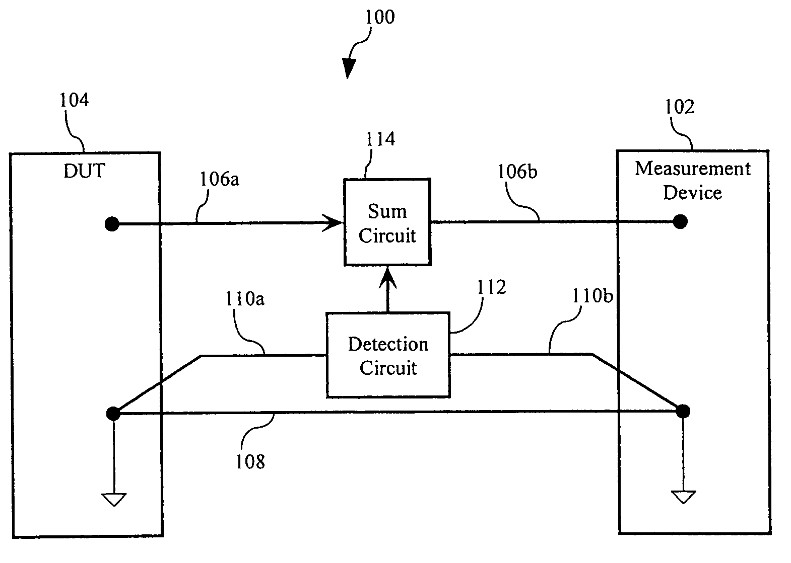
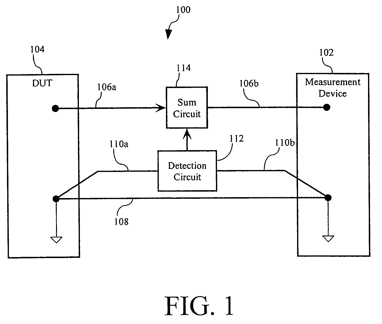
[0011]FIG. 1 is a simplified block diagram of a circuit 100 in accordance with the preferred embodiment of the present invention. It will be appreciated by those of ordinary skill in the relevant arts that the circuit 100, as illustrated in FIG. 1, and the operation thereof as described hereinafter is intended to be generally representative such systems and that any particular system may differ significantly from that shown in FIG. 1, particularly in the details of construction and operation of such system. As such, the circuit 100 is to be regarded as illustrative and exemplary and not limiting as regards the invention described herein or the claims attached hereto.

[0012]The circuit 100 generally comprises a measuring device 102 connected to a DUT 104. In accordance with the preferred e...


PUM


Abstract

A probe for connecting a device under test to a measurement device that corrects for dc errors and noise generated by the current flowing through the ground shield of a transmission line used by the probe. The probe identifies a voltage drop in the ground preferably using an additional line between the device under test and the measurement device. The signal provided to the measurement device is corrected based on the identified voltage drop.

Description

[0001]This is a Continuation of application Ser. No. 10 / 117,653, filed on Apr. 5, 2002, now U.S. Pat. No. 6,806,697, the entire disclosure of which is incorporated herein by reference.BACKGROUND OF THE INVENTION[0002]A probe is a device that ideally non-invasively connects a measurement device to a device under test (also referred to as a “DUT”). Known measurement devices, that utilize probes, include: oscilloscopes; spectrum analyzers; network analyzers; logic analyzers; counters; and time interval meters. In such known measurement devices, minimally invasive probes are connected to an indeterminate source of a signal to be tested and a ground of a DUT. To function in a minimally invasive manner, a probe has high impedance relative to the source impedance such that the probe does not add a significant load to the circuit under test. This feature separates probes from standard interconnects, such as used by power supplies and the like.[0003]Active probes are a class of probes that c...

Claims


Application Information

Patent Timeline
IPC IPC(8): G01R31/02G01R35/00G01R1/20
CPCG01R1/20
Inventor MCTIGUE, MICHAEL T.
Owner AGILENT TECH INC
Why Eureka
Try Eureka