Shaped illumination geometry and intensity using a diffractive optical element

a technology of optical elements and geometry, applied in the direction of optical radiation measurement, fluorescence/phosphorescence, spectrophotometry/monochromators, etc., can solve the problems of difficult to efficiently provide illumination and undesirable optical signals, and achieve the effect of greater degree of uniformity

Inactive Publication Date: 2006-02-28
APPL BIOSYSTEMS INC
View PDF46 Cites 36 Cited by
  • Summary
  • Abstract
  • Description
  • Claims
  • Application Information

AI Technical Summary

Benefits of technology

[0008]According to yet another aspect of the present invention, the inventive apparatus and method provide non-normal angle of incidence illumination of a selected area with a given light source with a greater degree of uniformity than is achieved when that light source is used to directly illuminate the selected area at the same non-normal angle of incidence.

Problems solved by technology

The resultant variance in optical signals may be undesirable.
However, it can be difficult to efficiently provide illumination having enhanced or a high degree of uniformity.

Method used


Image

  • Shaped illumination geometry and intensity using a diffractive optical element
  • Shaped illumination geometry and intensity using a diffractive optical element
  • Shaped illumination geometry and intensity using a diffractive optical element

Examples


Embodiment Construction

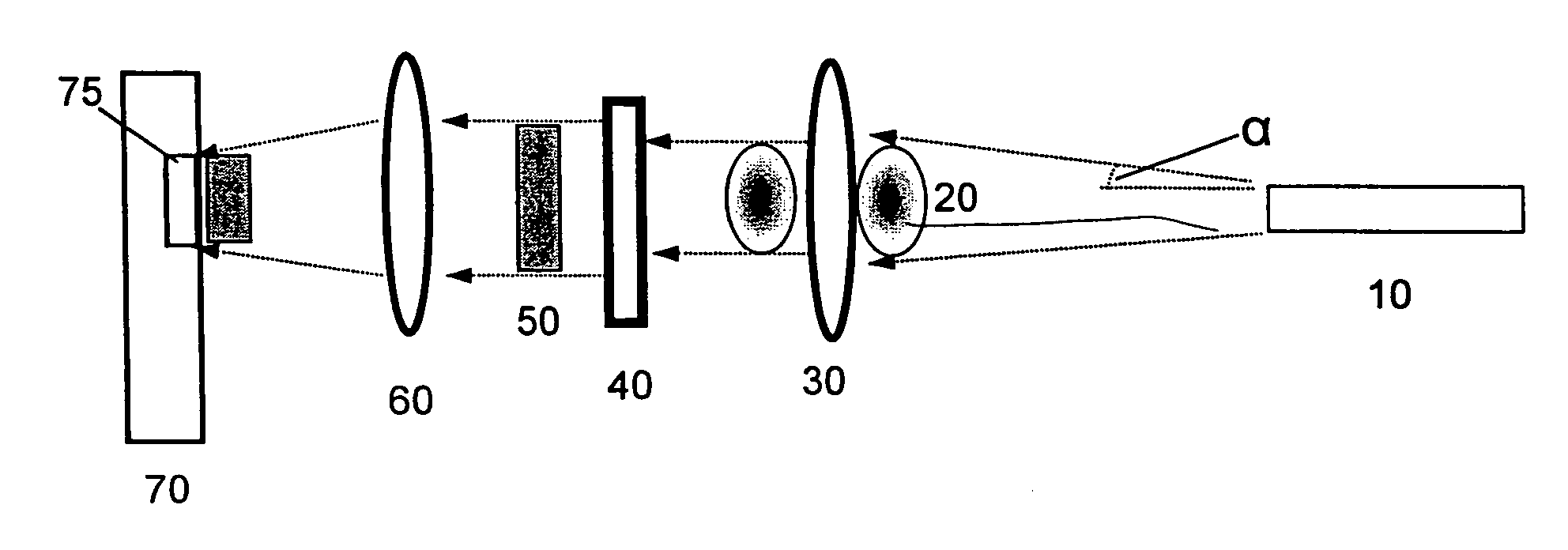
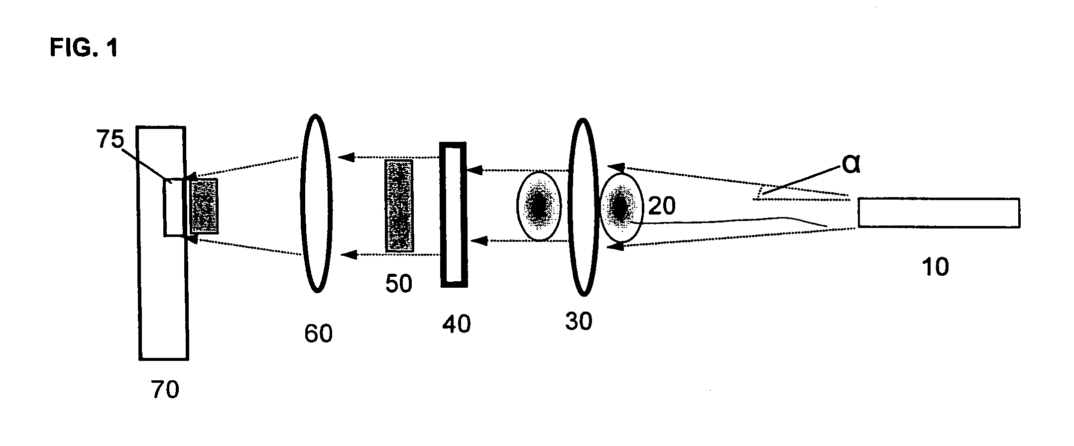
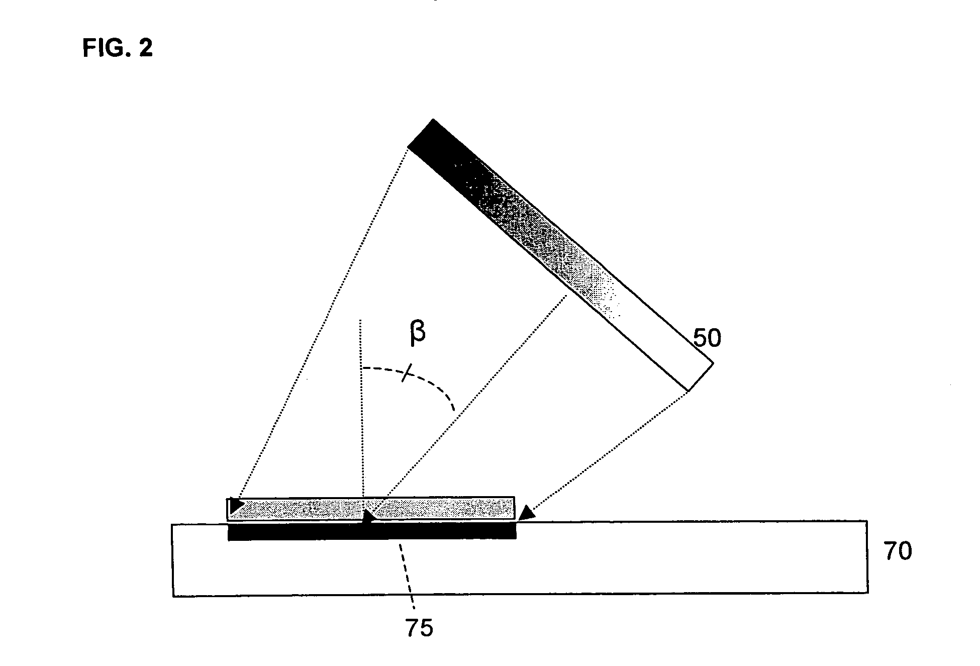
[0016]Reference will now be made in detail to certain embodiments of the invention, examples of which are illustrated in the accompanying drawings. Wherever possible, the same reference numbers will be used throughout the drawings to refer to the same or like parts.

[0017]The section headings used herein are for organizational purposes only, and are not to be construed as limiting the subject matter described. All documents cited in this application, including, but not limited to patents, patent applications, articles, books, and treatises, are expressly incorporated by reference in their entirety for any purpose.

[0018]It should be understood that the phrases “uniform illumination” and “uniformly illuminate,” as used herein with respect to the illumination of a selected region, refer to the variation in optical intensity of the light across the selected region. The lower the variation, the more uniform the illumination. Thus, uniform illumination can be characterized qualitatively as...


PUM

PropertyMeasurementUnit
diameteraaaaaaaaaa
diameteraaaaaaaaaa
areaaaaaaaaaaa

Abstract

A method and apparatus to illuminate a target. The apparatus can comprise a first lens configured to receive light from the light source, a diffractive optical element configured to receive the light from the first lens and to regulate the light into regulated light, and second lens configured to receive the regulated light and to direct the regulated light onto a selected area of the target.

Description

[0001]This is a continuation of application Ser. No. 09 / 964,778, filed Sep. 28, 2001 now U.S. Pat. No. 6,744,502, which is incorporated herein by reference.I. FIELD OF THE INVENTION[0002]This invention relates to methods and optical systems for illuminating a target. The present invention also relates to methods and systems for performing sample assays, and for producing and measuring optical responses and signatures.II. BACKGROUND OF THE INVENTION[0003]Targets, such as areas where optically transduced chemical and / or biochemical assays are performed, may need to be illuminated by a light source. It is often desirable to illuminate the target with light having enhanced uniformity of intensity over the entire target region. Optical signals are typically a function of the illumination intensity and, the more an illumination intensity varies across a target, the more the optical signal will also vary. The resultant variance in optical signals may be undesirable.[0004]However, it can be...

Claims


Application Information

Patent Timeline
Patent Type & Authority Patents(United States)
IPC IPC(8): G01J3/30G01J1/20G01N21/64G01J3/10G01N21/01G01N21/76G01N21/78
CPCG01J1/20G02B19/0014G02B27/0944G02B19/0052G02B27/0927G01J3/10
Inventor HOFF, LOUIS B.OLDHAM, MARK F.
Owner APPL BIOSYSTEMS INC
Why Eureka
Try Eureka