Slurry mixer constrictor valve

a constrictor valve and slurry mixer technology, applied in the direction of diaphragm valves, engine diaphragms, manufacturing tools, etc., can solve the problems of large muscle valves, high maintenance costs, and abrupt inlet and outlet orifices of pinch valves

Active Publication Date: 2006-03-07
UNITED STATES GYPSUM CO
View PDF4 Cites 86 Cited by
  • Summary
  • Abstract
  • Description
  • Claims
  • Application Information

AI Technical Summary

Benefits of technology

[0014]Accordingly, the above-listed needs are met or exceeded by the present apparatus and method for controlling the flow of a slurry including the feature of using a constrictor valve on a mixing and dispensing apparatus. The mixing apparatus is used to mix and agitate calcined gypsum and water to form an aqueous dispersion or slurry of the calcined gypsum. After the contents are agitated, the contents are passed through the outlet of the mixer to the dispensing apparatus. The dispensing apparatus preferably includes an elongate, preferably flexible conduit which provides additional space for the uniform mixing of slurry. By providing the constrictor valve on the flexible conduit, a back-pressure is created on the mixture causing an increase in the volume of the mixture in the mixer when the conduit is constricted. Unwanted premature setting of gypsum is prevented when the conduit is constricted so that occurrences of lumps are reduced.

Problems solved by technology

However, the pinch valve deforms the conduit into a flattened or rectangular orifice which is susceptible to plugging from prematurely setting slurry in the flow, particularly in the corners of the orifice, where the flow velocity is lower.
Further, the inlet and outlet orifices of the pinch valve are abrupt because pressure is exerted on the conduit in a substantially singular plane and does not allow for a gradual transition.
Such abrupt entrances and exits can lead to further plugging of slurry producing equipment, which causes costly downtime for repairs.
Further, the muscle valves frequently are massive in size which limits the operator's access to the orifice for clearing a plug or buildup, or for general observation of the flow of slurry through the channel itself.
Similar problems are seen in the use of these valves as are exhibited with the muscle valves and the pinch valves.
In particular, solids easily build up, forming crystalline gypsum, which then prematurely sets and causes further clogging of the apparatus.
Further, the prior art valves cannot easily reproduce exact settings which correspond to a given amount of restriction of the conduit.
Further still, the prior art valves do not have interchangeable parts, nor are they adapted to be used with different sized conduits.

Method used


Image

  • Slurry mixer constrictor valve
  • Slurry mixer constrictor valve
  • Slurry mixer constrictor valve

Examples


Embodiment Construction

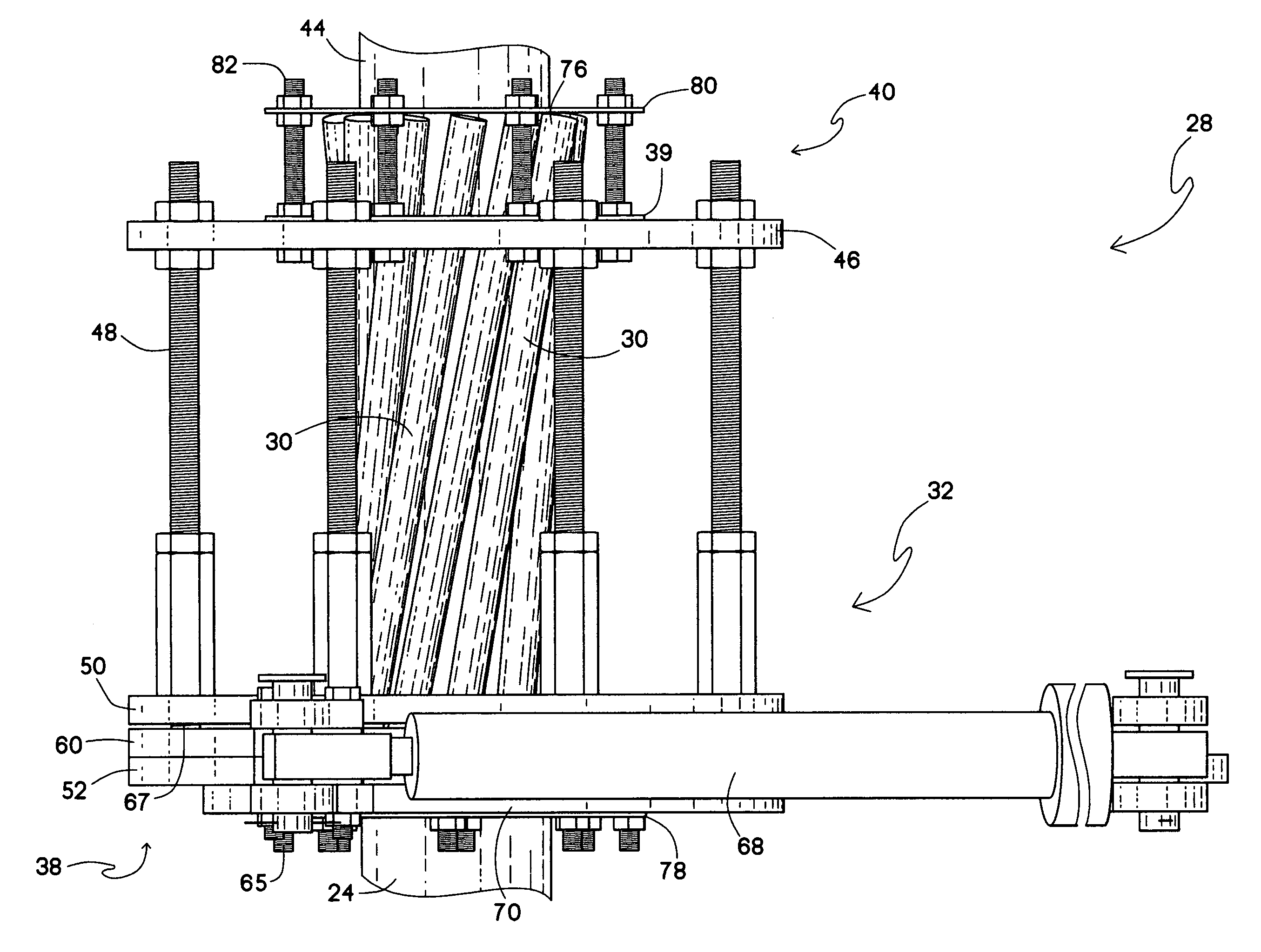
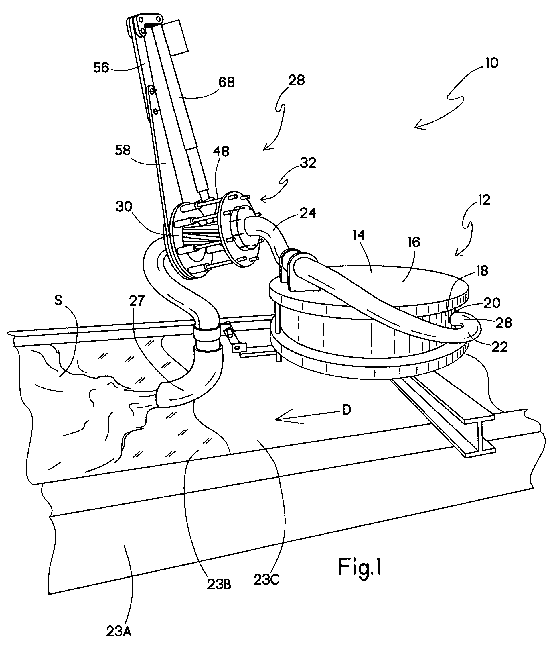
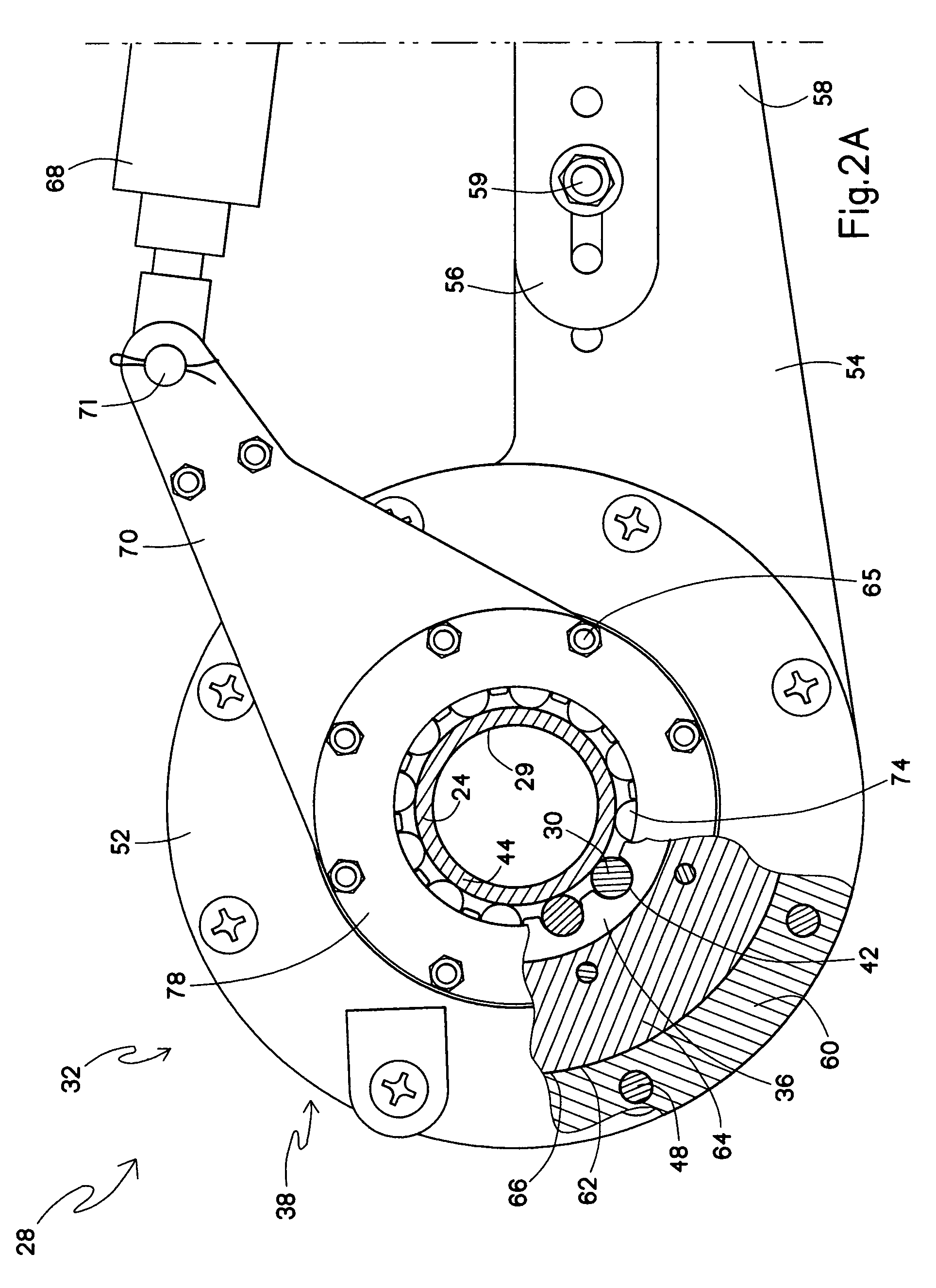
[0028]Referring now to FIG. 1, a mixing apparatus for mixing and dispensing a slurry is generally designated 10 and includes a mixer 12 having a mixer motor 13 and a housing 14 configured for receiving and mixing the slurry. The housing 14 defines a chamber (not seen) for holding the slurry, and has a preferably generally cylindrical shape. The housing 14 has an upper wall 16, a lower wall (not seen) and an annular peripheral wall 18. Calcined gypsum and water, as well as other materials or additives often employed in slurries to prepare gypsum products, are mixed in the mixing apparatus 10.

[0029]An outlet 20, also referred to as a mixer outlet, a discharge gate or a slot, is provided in the peripheral wall 18 for the discharge of the major portion of the well-mixed slurry into what is generally referred to herein as a dispensing apparatus 22.

[0030]The dispensing apparatus 22 includes an elongate, preferably cylindrical flexible, resilient tube or conduit 24 having a main inlet 26 i...


PUM

PropertyMeasurementUnit
thicknessaaaaaaaaaa
diameteraaaaaaaaaa
velocityaaaaaaaaaa

Abstract

An apparatus and method for controlling the flow of a slurry is provided which includes using a constrictor valve on a mixing and dispensing apparatus. The constrictor valve includes a first guide plate and a second guide plate that are spaced a distance apart along the length of the conduit. Extending between the two guide plates, a plurality of elongate members have first and second ends engaged on the first and second guide plates. Upon rotation of at least one of the first and second guide plates, the elongate members are configured to impart pressure on, and constrict the conduit.

Description

BACKGROUND ART[0001]The present invention relates to a method and apparatus for preparing gypsum products (i.e., products comprising calcium sulfate dihydrate) from starting materials comprising calcined gypsum (i.e., calcium sulfate hemihydrate) and water. More particularly, the present invention relates to an improved valve on a conduit located downstream of the slurry mixer and typically used to supply agitated gypsum slurry to a wallboard production line. The basic technology of gypsum wallboard manufacture is disclosed in U.S. Pat. Nos. 1,500,452; 2,207,339 and 4,009,062 all of which are incorporated by reference herein. The present apparatus provides an improved flow of slurry from the dispensing system which enhances the uniform smoothness of the gypsum slurry at the wallboard production line.[0002]It is well known to produce gypsum products by uniformly dispersing calcined gypsum in water to form a slurry and then casting the slurry into a desired shaped mold or onto a surfa...

Claims


Application Information

Patent Timeline
Patent Type & Authority Patents(United States)
IPC IPC(8): F16K7/04B28B19/00B28C7/16F16K7/06
CPCF16K7/06B28C7/16B28B19/0092F16K7/02F16K7/04
Inventor PETERSEN, BRUCE LYNNHASZEL, RICHARD JAMESWITTBOLD, JAMES R.
Owner UNITED STATES GYPSUM CO
Why Eureka
Try Eureka