Card connector

a card connector and connector technology, applied in the direction of coupling device connection, coupling/disconnecting parts, electrical apparatus, etc., can solve the problems of unstable signal transmission, improper contact between the conductive terminal and the mainboard, and the inability to fix the electronic card

Inactive Publication Date: 2006-03-07
L&K PRECISION TECH CO LTD
View PDF8 Cites 18 Cited by
  • Summary
  • Abstract
  • Description
  • Claims
  • Application Information

AI Technical Summary

Benefits of technology

[0005]Accordingly, an object of the present invention is to provide a card connector which guides an electronic card inserted in or ejected out and which firmly retains the card when the card reaches a predetermined final position thereby effectively protecting from exterior shock and assuring reliable signal transmission.
[0009]The slider is cantileveredly mounted on the driving rod. An abutting portion is formed at a free end of the slider and near the stop block of the driven sleeve for abutting the stop block when assembled together. During insertion of the card, the driving rod drives the driven shaft to rotate. The stop block of the driven sleeve, which abuts the abutting portion of the slider in normal state, disengages from the abutting portion, and thereafter engages with a wedging hole of the card. Thus, the card in the final position is protected against exterior reverse shock.

Problems solved by technology

However, the electronic card cannot be fixed when it is received in the eject device.
Especially under undesired environment or exterior shock, the card tends to displace, resulting in improper contact between the conductive terminals and the mainboard and even unstable signal transmission.
Additionally, in such a design, the conductive terminals are apt to wear down.

Method used


Image

  • Card connector
  • Card connector
  • Card connector

Examples


Embodiment Construction

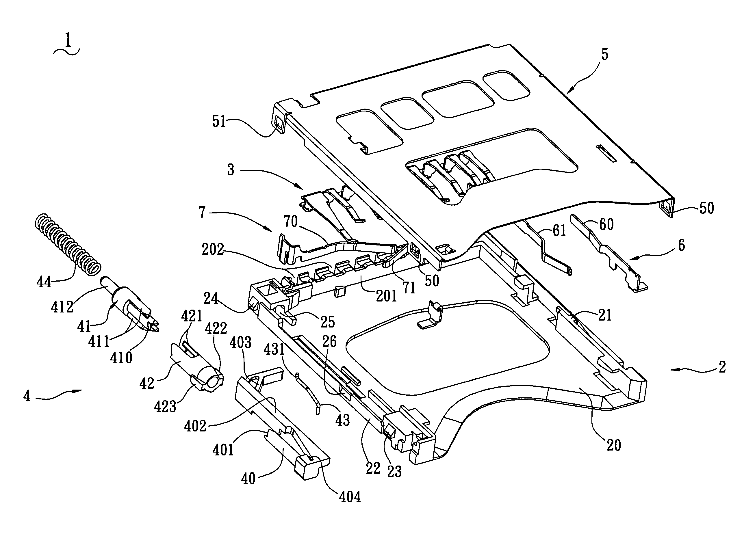
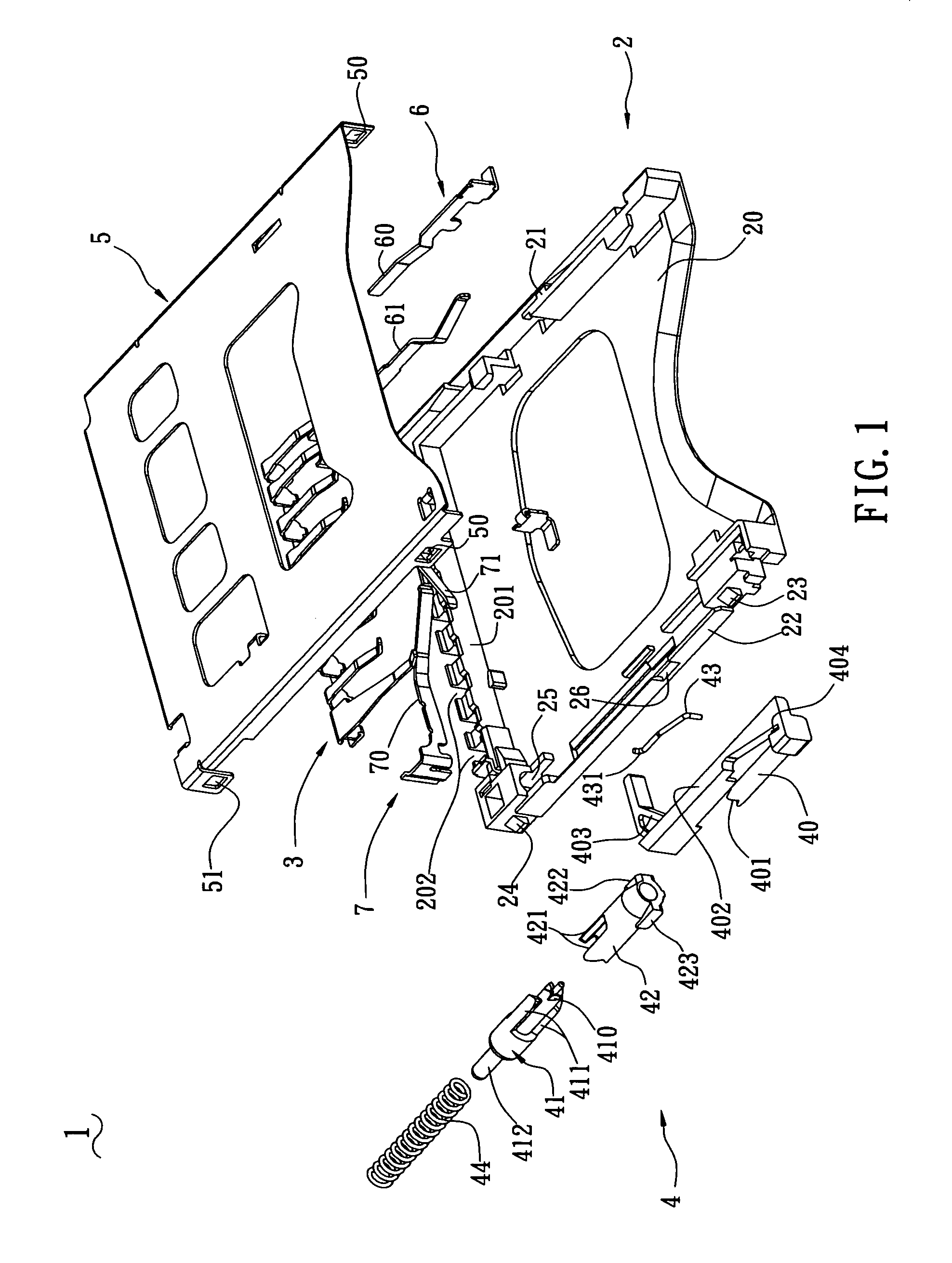
[0017]With reference to FIG. 1, a card connector 1 of the present invention comprises an insulative frame 2, a plurality of conductive terminals 3 received in the insulative frame 2, an eject device 4 and a shell 5.

[0018]The insulative frame 2 includes a housing 20 and a pair of side posts 21, 22 at opposite sides of the housing 20. The housing 20 forms a bottom post 201, and defines a plurality of passageways 202 in the bottom post 201 for receiving the conductive terminals 3 therein. The side posts 21, 22 and the bottom post 201 borders a receiving slot (not labeled) for accommodating an electronic card 8 (shown in FIG. 4) therein. A first switch 6 is mounted on the housing 20 for write-protect enabling of the card 8. The first switch 6 has a pair of spring sheets 60, 61 which are constantly open in normal state. Namely, when assembled, the spring sheets 60, 61 do not contact each other until the card 8 is inserted to provide pressure. A second switch 7 is mounted on the housing 2...


PUM


Abstract

A card connector has an insulative frame, a plurality of conductive terminals received in the insulative frame, an eject device assembled on the insulative frame and a shell covering the insulative frame. The eject device includes a driving rod, a driven shaft, a driven sleeve, a slider and a resilient element. The driving rod axially defines a 90 degree first continuous chute, and the driven shaft axially defines a 90 degree second continuous chute for meshing with the first continuous chute. The driven sleeve is fixed on the insulative frame and telescopically meshes with the driven shaft. The slider is cantileveredly mounted on the driving rod. During insertion of the card, the driving rod drives the driven shaft to rotate. A stop block of the driven sleeve disengages from an abutting portion of the slider, and thereafter engages with a wedging hole of the card. Thus, the card in final position is protected against exterior reverse shock.

Description

BACKGROUND OF THE INVENTION[0001]1. Field of the Invention[0002]The present invention relates to a card connector, and particularly to a card connector which is used to communicate between an electronic card and a mainboard and which allows the card inserted in or ejected out only by pressing the electronic card.[0003]2. Related Art[0004]Push—Push type connectors are often used to communicate between an electronic card and a mainboard, which allows the card inserted in or ejected out only by pressing the electronic card. U.S. Pat. No. 6,520,784 discloses such a card connector. The card connector includes a connector body receiving a plurality of terminals therein, an eject device assembled on the connector body for guiding an electronic card inserted in or ejected out, and a metal shell for covering the housing. However, the electronic card cannot be fixed when it is received in the eject device. Especially under undesired environment or exterior shock, the card tends to displace, r...

Claims


Application Information

Patent Timeline
Patent Type & Authority Patents(United States)
IPC IPC(8): H01R13/62
CPCH01R13/629
Inventor CHIEN, HSU-PIN
Owner L&K PRECISION TECH CO LTD
Why Eureka
Try Eureka