Terminal assembly for vented circuit breaker and circuit breaker incorporating same

Inactive Publication Date: 2006-03-07
EATON CORP
View PDF21 Cites 29 Cited by
  • Summary
  • Abstract
  • Description
  • Claims
  • Application Information

AI Technical Summary

Benefits of technology

[0010]The invention also embraces a terminal assembly for a circuit breaker having a housing with an external terminal recess and a vent opening for discharging arc gases into the terminal recess and a main conductor extending out of the housing adjacent the vent opening and into the terminal recess for connection to an external conductor. This terminal assembly comprises a terminal collar in the external terminal recess through which the main conductor extends. An electrically conductive stand is positioned in the collar with the first surface in contact with the main conductor and having a transverse through opening aligned with the vent opening in the housing. A terminal screw threaded through the terminal collar toward the main conductor clamps the external conductor against a second surface of the electrically condu

Problems solved by technology

In the typical circuit breaker, some of the arc gases are reflected off walls of the circuit breaker housing, which slows arc transfer from the contacts to the arc chute and reduces the discharge rate of arc gase

Method used


Image

  • Terminal assembly for vented circuit breaker and circuit breaker incorporating same
  • Terminal assembly for vented circuit breaker and circuit breaker incorporating same
  • Terminal assembly for vented circuit breaker and circuit breaker incorporating same

Examples


Embodiment Construction

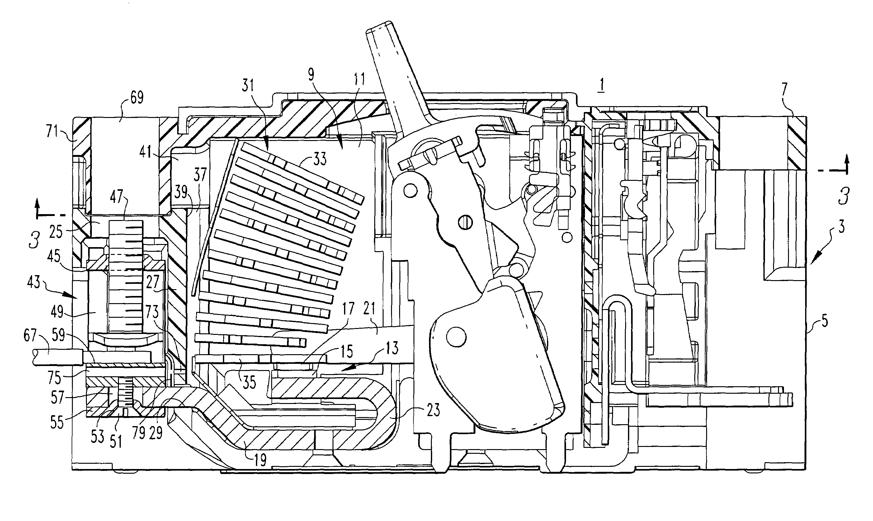
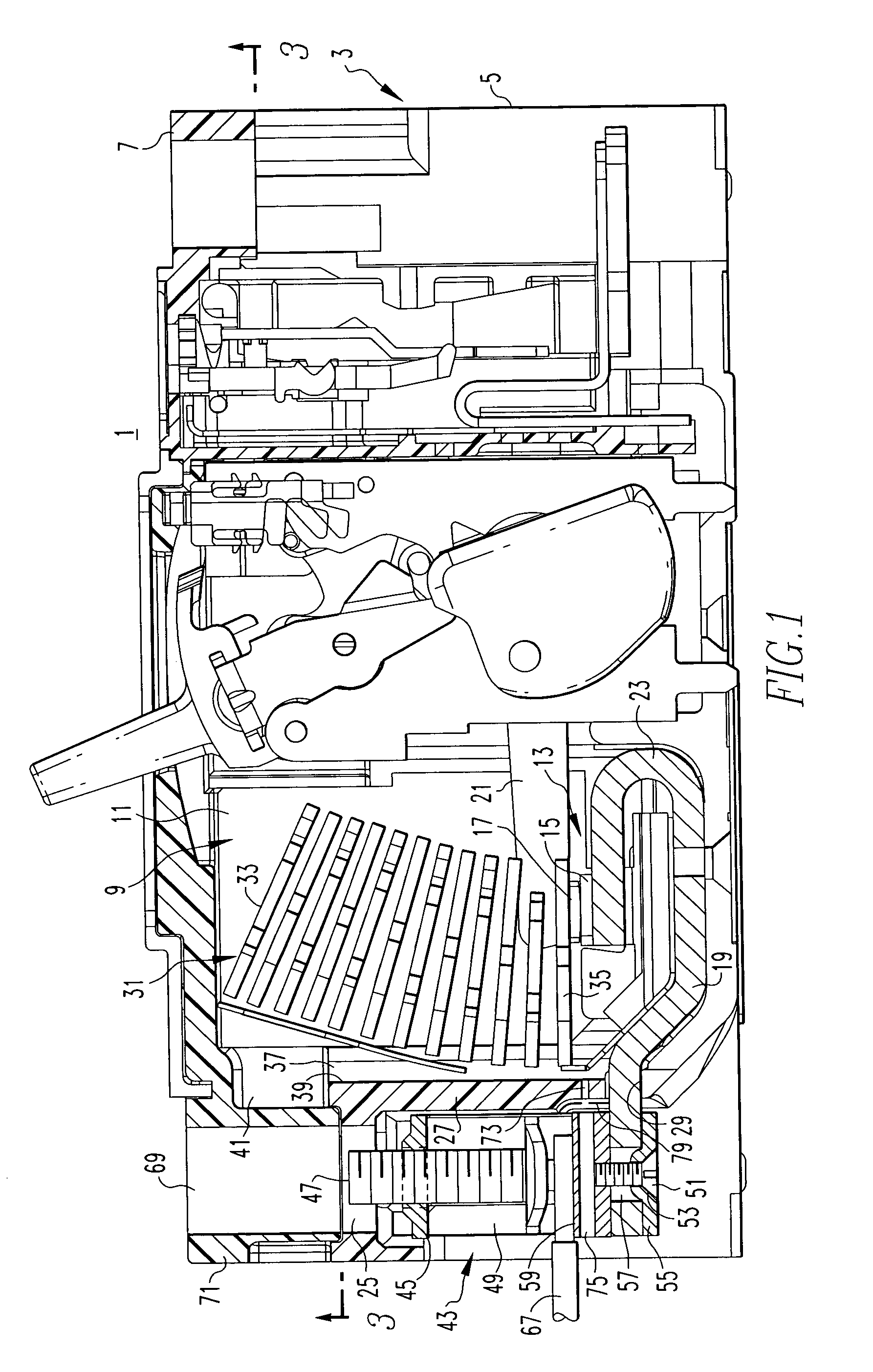
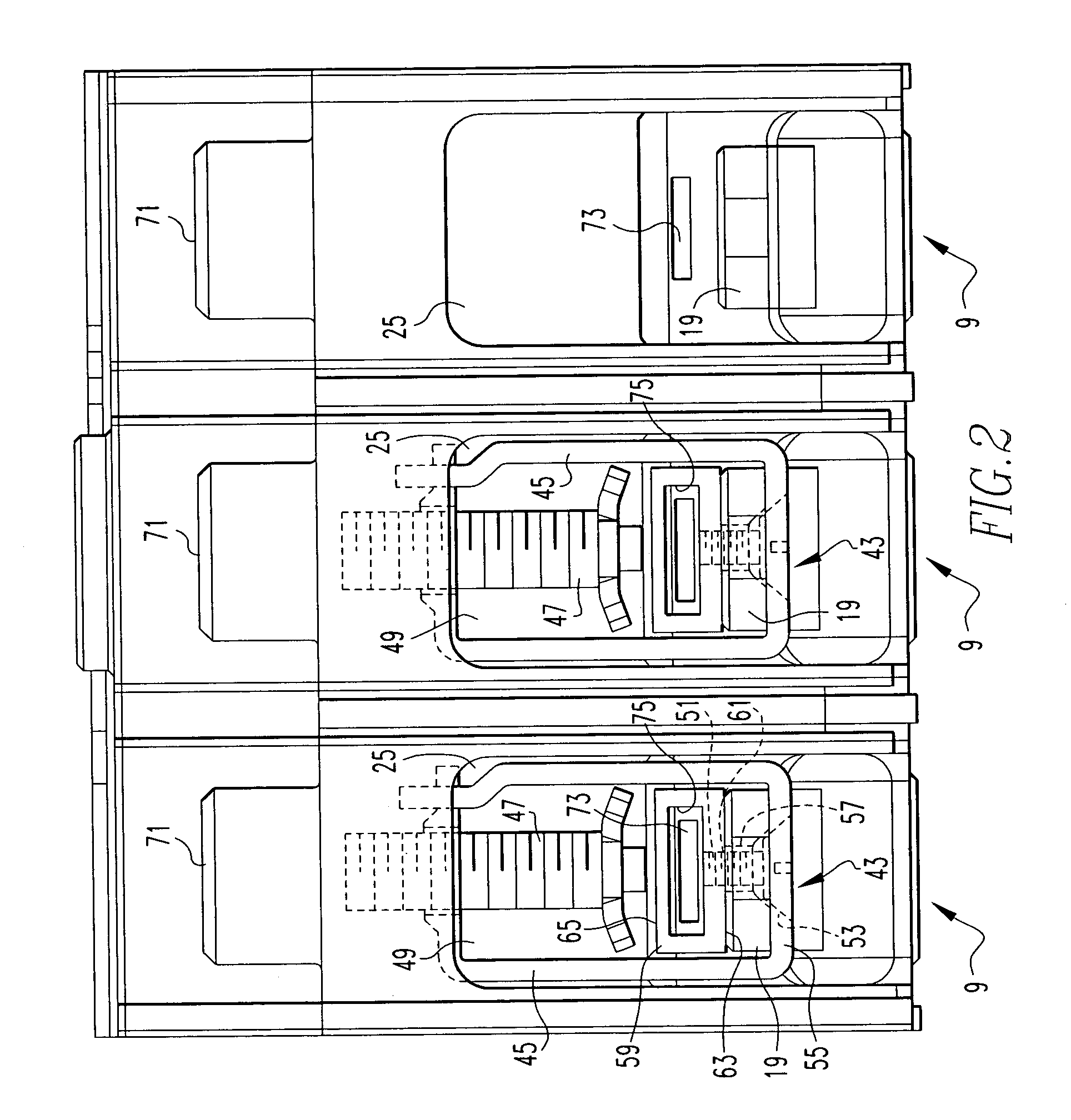
[0016]Referring to FIG. 1, a circuit breaker 1 has a molded housing 3 having a base 5 and cover 7. The particular circuit breaker 1 is a three pole breaker. Accordingly, the housing 3 has for each pole 9 an internal contact cavity 111 containing separable contacts 13 including a fixed contact 15 and a movable contact 17. The fixed contact 15 is mounted on a line side main conductor 19 while the movable contact 17 is mounted on the free end of a pivotally mounted contact arm 21. The contact arms 21 of all of the poles 9 are simultaneously rotated from a closed position in which the separable contacts are closed shown in FIG. 1 to an open position (not shown) by an operating mechanism (not shown) in a well known manner. The line side main conductor 19 is formed with a reverse loop 23 to generate repulsion forces between the oppositely flowing currents in the reverse loop 23 and the contact arm 21 to aid in rapid opening of the separable contacts in response to high overcurrents, again...


PUM


Abstract

A circuit breaker vents at least some of the arc gases generated during current interruption from an internal cavity containing separable contacts through a terminal recess vent in a wall in the housing into an external terminal recess. The line side main conductor extends through the same wall into the external terminal recess adjacent the vent and into the collar of a terminal assembly. An electrically conductive stand seated on the main conductor electrically connects to the main conductor an external conductor clamped against the stand by a terminal screw threaded through the collar. The stand has a through opening aligned with the terminal recess vent to pass the arc gases through the external terminal recess to atmosphere.

Description

BACKGROUND OF THE INVENTION[0001]1. Field of the Invention[0002]This invention relates to circuit breaker and more particularly to extinguishing arcs generated during high current interruption through a terminal assembly that improves arc gas discharge.[0003]2. Background Information[0004]The current interruption capability of air circuit breakers is dependent in part upon their ability to extinguish the arc that is generated when the circuit breaker main contacts open. Even though the contacts separate, current continues to flow through the ionized gases formed by vaporization of the contacts and surrounding materials. The arc is extinguished through transfer to a set of stacked metal plates in an arc chute that break the arc into a series of arcs, thereby raising the electrical resistance of the arc with a commensurate increase in arc voltage and a reduction in arc current. The arc is also cooled by the flow of the arc gases induced by venting and through vaporization of the metal...

Claims


Application Information

Patent Timeline
IPC IPC(8): H01H33/02
CPCH01H9/342H01R4/363H01H71/08H01H1/5855H01H2001/5861
Inventor SHEA, JOHN J.CHOU, YU WEI
Owner EATON CORP
Why Eureka
Try Eureka