Optical probe for scanning the features of an object and methods therefor

a technology of optical probes and features, applied in the field of optical scanning technology, can solve the problems of inaccurate and inaccurate machine measurement speed, affecting the accuracy of the object, and the pattern might become distorted on the object,

Inactive Publication Date: 2006-03-07
3D SCANNERS LTD +1
View PDF14 Cites 56 Cited by
  • Summary
  • Abstract
  • Description
  • Claims
  • Application Information

AI Technical Summary

Problems solved by technology

However, these machines lack flexibility and measuring speed.
They are quite inaccurate and are not suited for highly curved three-dimensional parts.
The pattern might become distorted on the object due to the relief of the object and the angle of the probe relative to the object.
Probes of the prior art which are mounted on a localizer have a single light source, one or two viewing directions, one projection direction and a line, fringes or black-white stripes in the pattern direction for moire analysis; these probes are inaccurate, and when they are used for measuring features in objects, they are slow and have to be reoriented several times by the localizer in order to measure the features properly.
In both cases, translational and / or rotational movements of the probe required to scan a hole or circle are mechanically complicated.
The use of two or more viewing directions in some laser scanners, reduces the chances of line of sight between the receiving optics and the part of the object that is highlighted by the laser becoming blocked by a part of the object itself during scanning.
This implies that translational movements of the line laser scanner made by the localizer in general are not by themselves sufficient to accurately measure the feature; rotational movements of the scanner would be necessary.
However, and as already mentioned above, the approach comprising translational and rotational movements of the laser scanner is mechanically complicated.
Due the limited depth of view of the optical arrangement in the viewing direction it is difficult to obtain an accurate image of all the projected patterns simultaneously with only one viewing direction.
If one projection direction with a complex pattern is used, it is difficult to achieve a good accuracy of feature measurement, even with multiple viewing directions over the complete pattern.

Method used


Image

  • Optical probe for scanning the features of an object and methods therefor
  • Optical probe for scanning the features of an object and methods therefor
  • Optical probe for scanning the features of an object and methods therefor

Examples


Embodiment Construction

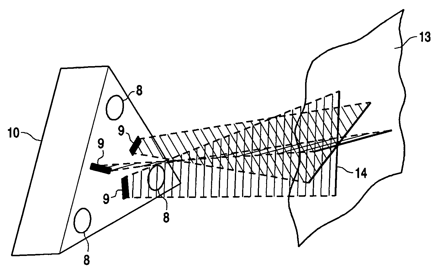
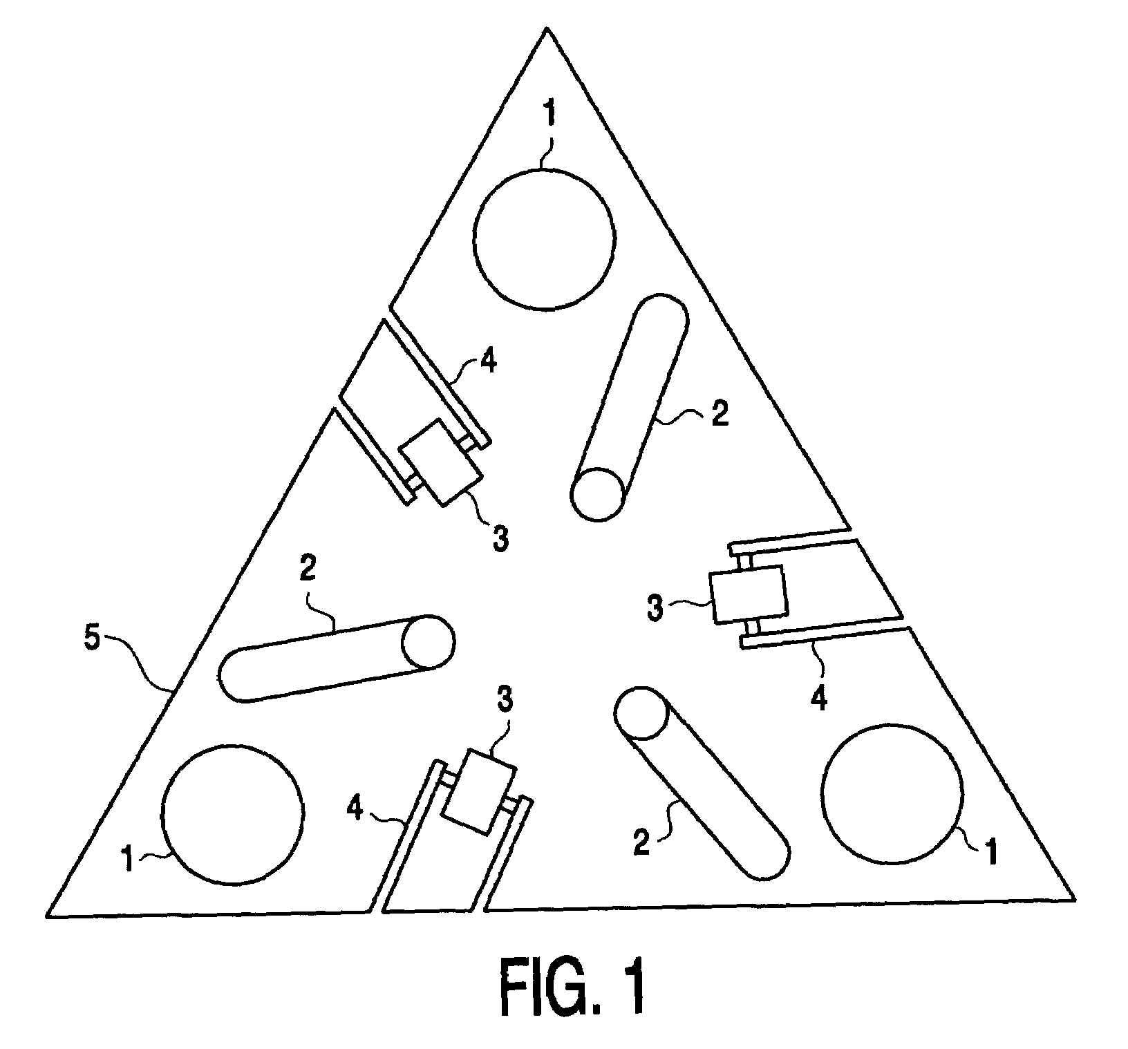
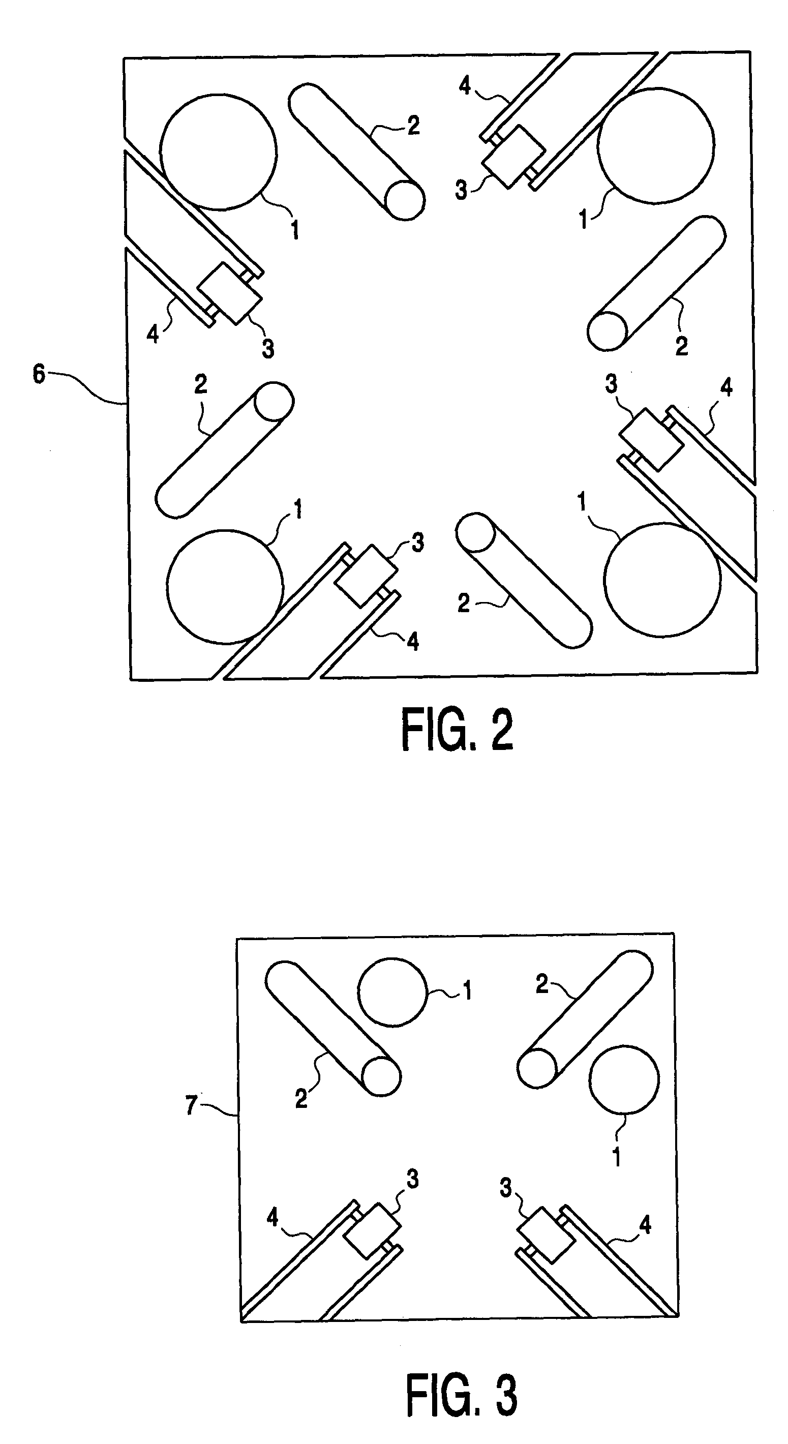
[0016]One embodiment of the present invention is a method for measuring the features of an object using an optical probe comprising more than one projection directions and more than one viewing directions comprising a) configuring the optical probe into two or more optical groups, wherein an optical group comprises one or more viewing directions and one or more projection directions, and wherein at least one viewing direction and at least one projection direction is different between the optical groups, wherein data obtained by the viewing directions is generated only from patterns projected by the projection directions of the same optical group; b) collecting data from each optical group while scanning the object; and c) obtaining a measurement of the features of the object from the collected data.

[0017]Another embodiment of the present invention is a method as described above wherein each the optical group of the optical probe has part of its one dimensional, two dimensional or th...


PUM

PropertyMeasurementUnit
angleaaaaaaaaaa
angleaaaaaaaaaa
angleaaaaaaaaaa

Abstract

An optical probe for measuring features of an object comprises two or more viewing directions and two or more projection directions. A method of measuring the features of an object comprises configuring an optical probe into two or more optical groups, wherein an optical group comprises one or more viewing directions and one or more projection directions, wherein at least one viewing direction and at least one projection direction is different between the optical groups, and wherein data obtained by the viewing directions is generated only from patterns projected by the projection directions of the same optical group. The method further comprises collecting data from each optical group while scanning the object.

Description

CROSS REFERENCE TO RELATED APPLICATION[0001]This application claims priority to U.S. Provisional Patent Application 60 / 420,909 entitled “CROSS LASER SCANNER” and filed on Oct. 23, 2002. The disclosure of the above-described filed application is hereby incorporated by reference in its entirety.BACKGROUND OF THE INVENTION[0002]1. Field of the Invention[0003]The present invention relates to the field of optical scanning technology. One aspect the present invention relates to an optical probe optionally for use on a localizer. In another aspect, the present invention relates to a method for scanning an object using the optical probe according to the invention, optionally connected to a localizer.[0004]2. Description of the Related Art[0005]In order to optically measure the position and the dimensions of features in industrial objects such as holes, slots, edges or gap and flush, different solutions presently exist. For example, there are dedicated measuring machines such as profile proj...

Claims


Application Information

Patent Timeline
Patent Type & Authority Patents(United States)
IPC IPC(8): G01B11/24G01B11/14G01B11/30G01N21/86B25J9/16G01B11/00G01B11/25
CPCG01B11/002G01B11/2545G01B11/2513
Inventor VAN COPPENOLLE, BARTDE JONGE, LIEVENVALLONS, KRISTHYS, FRANK
Owner 3D SCANNERS LTD
Why Eureka
Try Eureka