
Pressure assisted dual flush operating system

a dual-flush, pressure assisted technology, applied in flushing devices, water installations, constructions, etc., can solve the problems of excessive pressure over strictly preset limits, potential safety concerns, and excessive or too little refill volume, so as to achieve a comparatively larger opening diameter

Active Publication Date: 2006-03-14
LI FEIYU
View PDF11 Cites 23 Cited by
  • Summary
  • Abstract
  • Description
  • Claims
  • Application Information

AI Technical Summary

Benefits of technology

[0021]7. The present invention has self-cleaning function. Since the inlet of the dual flush valve of present invention does not control the drop speed of the bottom piston, the diameter of the opening can be designed comparatively larger. In order to control the drop speed of the bottom piston, a guide slot is attached to the slide bar of the bottom piston. The radius of the guide slot is designed so as to control the descending speed of the bottom piston. During the actuation of the bottom piston, the fluid flows cleans the guide slot and is an additional feature of the invention.

Problems solved by technology

In such a system, however, there are some problems as follows:1. The flush valve of the system has only one single flush function.
Any excess pressure over the strictly preset limitation may be dangerous.
Therefore, there is potential safety concern if there was only one discharge protector used.3. The refill rate is not adjustable.
The refill volume may be too much or too little when the system is used with differently designed toilet bowls.4. The flush valve cannot be shut off when a low pressure occurs in the water supply pipe, and this may cause water leaking from the pressure vessel.
Therefore, a cleaning device needs to be attached, which complicates the structure.
Other partial flush systems have been implemented, but have not been implemented with a pressurized flushing system.

Method used


Image

  • Pressure assisted dual flush operating system
  • Pressure assisted dual flush operating system
  • Pressure assisted dual flush operating system

Examples


Embodiment Construction

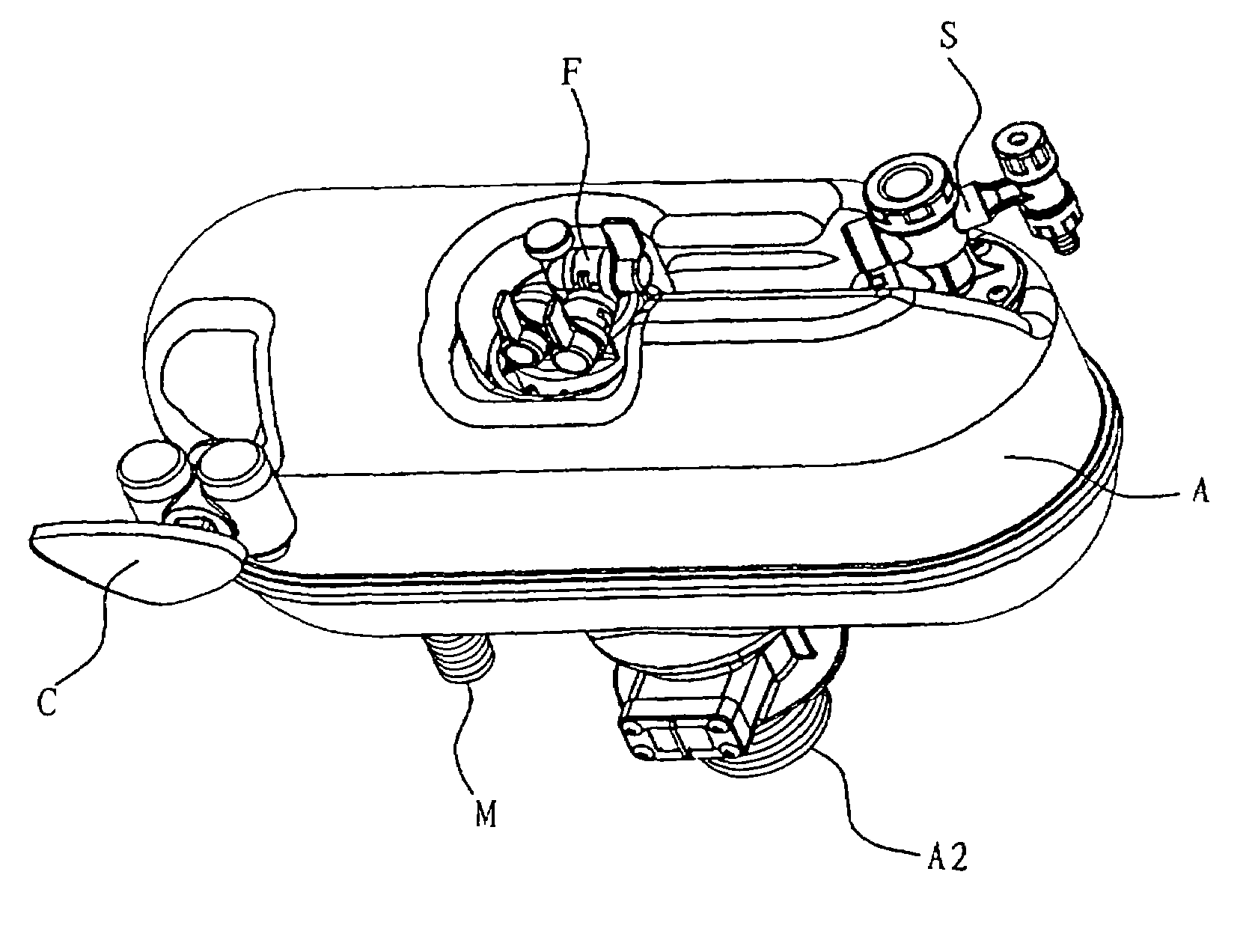
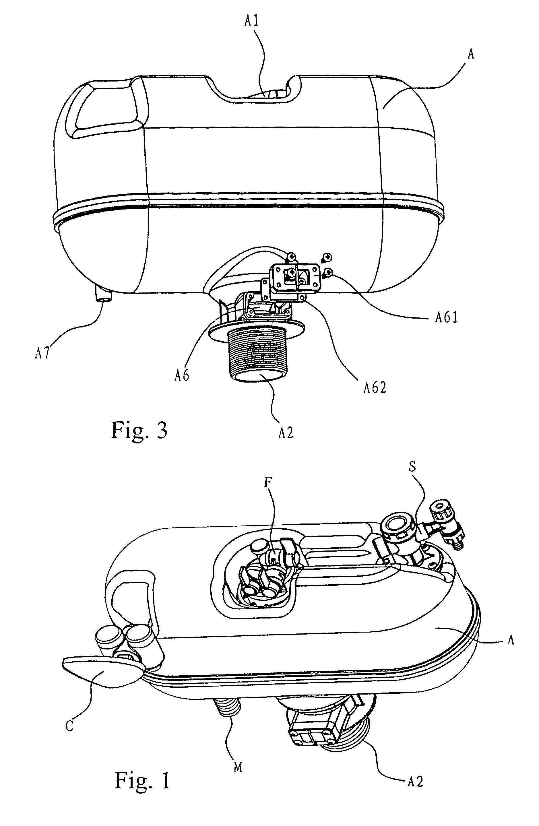
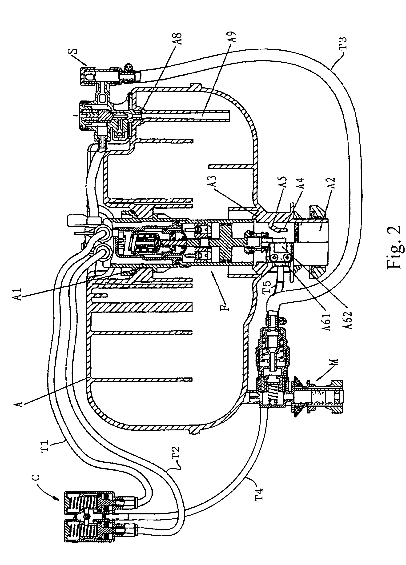
[0049]As is shown in FIG. 1 and FIG. 2, the invention includes the pressure water vessel A, the infill valve M, the air-in valve S, the dual flush valve F and the dual flush control valve C. The infill valve M is fixed in the lower left of the pressure water vessel A. The air-in valve S is fixed in the upper right of the pressure water vessel A The dual flush valve F is fixed through the middle of the pressure water vessel A. The dual flush control valve C can be installed in any position of a toilet tank (not shown in the Figs.), namely the either front side, side or top of the toilet tank as hereinabove noted.

The Pressure Water Vessel A (Please Refer to the FIG. 1 to 3)

[0050]The pressure water vessel A is a sealed container made of high-strength and high-stability material. An opening A1 is set above the center of vessel A with some projections around its brim. The outlet A2 is set under the opening A1 and some external threads are set in the peripheral lower section of the outlet...


PUM


Abstract

A pressure assisted dual flush operating system includes a vessel for receiving, containing and discharging pressurized water and an outlet for discharge of water from said vessel. An anti-siphon valve includes an air inlet for introducing water into said vessel and an inlet valve is provided for admitting water to the anti-siphon valve. A dual flush valve selectively releases different quantities of water from said vessel through the vessel outlet and a control valve selects one of the different quantities of water released by the dual flush valve.

Description

[0001]This application claims priority from provisional application 60 / 460,550 filed Apr. 4, 2003.FIELD OF THE INVENTION[0002]The invention relates to a toilet flush system, more particularly a pressurized dual flush system.BACKGROUND OF THE INVENTION[0003]A conventional pressure flush system uses a pressure water vessel disposed inside a toilet water tank. When water is infused into the vessel, the air in the water vessel is compressed and pressure accumulates inside the vessel. When a flush is needed, a user discharges the pressurized water through a discharge valve and through a toilet bowl trapway in order to provide a flushing action.[0004]Thus, a pressure flush system utilizes compressed air to drive water into the bowl instead of the “pulling” or siphon action of gravity style toilets. As the result, a little amount of water provides a full and effective flushing of the pressure flush toilet.[0005]The typical structure of a prior art pressure flush system is described in pate...

Claims


Application Information

Patent Timeline
Patent Type & Authority Patents(United States)
IPC IPC(8): E03D3/10E03D3/12
CPCE03D3/12E03D3/10
Inventor LI, FEIYU
Owner LI FEIYU
Learn More